
Choose a battery format by comparing the complete supported arrangement, its route into the building and the service task it must allow. Rack modules can suit projects that share an approved module and accessory system. A wall enclosure can release floor area where the structure and mounting design are suitable. An upright cabinet can avoid a wall-hanging installation where the floor, restraint and handling route are suitable. None of those advantages follows from the enclosure shape alone.
For a distributor, the decision continues after the first installation. The configuration placed in stock determines which supports and cables an installer receives, what can be expanded later and what must travel back if a unit needs service. A smaller replaceable item may simplify part of that job while leaving shutdown, lifting and recommissioning work unchanged.
This guide compares low-voltage LiFePO4 home-battery formats using published ZJBESS products and clearly identified illustrations. It does not prescribe lifting, fixing or electrical work. The appropriate product documents and qualified site assessment determine the actual installation.

Define what the mounting label includes
A rack-mounted battery is intended for a compatible rack, cabinet or specified support arrangement. The module and the rack are separate purchasing objects unless the offer expressly combines them. A wall-mounted battery uses its specified supporting structure and mounting hardware. A floor-standing cabinet transfers its installed load through the floor or an approved base, with any required restraint still part of the design.
These are overlapping descriptions. A rack can stand on the floor, and a modular battery can be installed inside a wall-mounted enclosure. For example, Pytes lists wall and floor mounting for its R-BOX enclosure. That is an example of one manufacturer’s arrangement, not permission to install a ZJBESS module in that enclosure.
Start the comparison with the object being supplied: one bare module, a populated rack, an integrated battery cabinet or an assembled stack with its base and control parts. “One battery” can mean different objects on different quotations. That ambiguity affects delivery weight, support hardware, usable connection space and the unit sent out as a replacement.
| Proposed arrangement | What carries or restrains it | A decision the label cannot settle |
| Modules in a rack | Specified shelves, rails or other supports and the complete rack arrangement | Whether that exact module, connector clearance and loaded rack are suitable |
| Wall-mounted enclosure | Approved bracket, fixings and supporting wall or structure | Whether the wall and the approved lifting/removal movement are available |
| Upright floor cabinet | Floor or base plus any specified restraint | Whether the delivery route, positioning and later replacement can be completed |
| Low-profile or stacked product | Its approved orientation, base, supports and assembled configuration | Whether the space above it is usable or further modules may be added |
The format also does not establish outdoor suitability. Enclosure protection, permitted environment and installation conditions are separate evidence. Direct sun, moisture, cable-entry arrangements and service access can remain relevant even where a product has an IP declaration. Use the model’s own conditions rather than turning an enclosure rating into a general location approval.
Check rack support and connections as one arrangement
Matching a front width is only the beginning of rack fit. Usable depth must accommodate the battery body and the required connection arrangement. The door, rear panel or another module can occupy space needed for a connector, its permitted cable route or access to a disconnect. Mounting ears and front handles show physical features; they do not identify the complete load-bearing or lifting method.
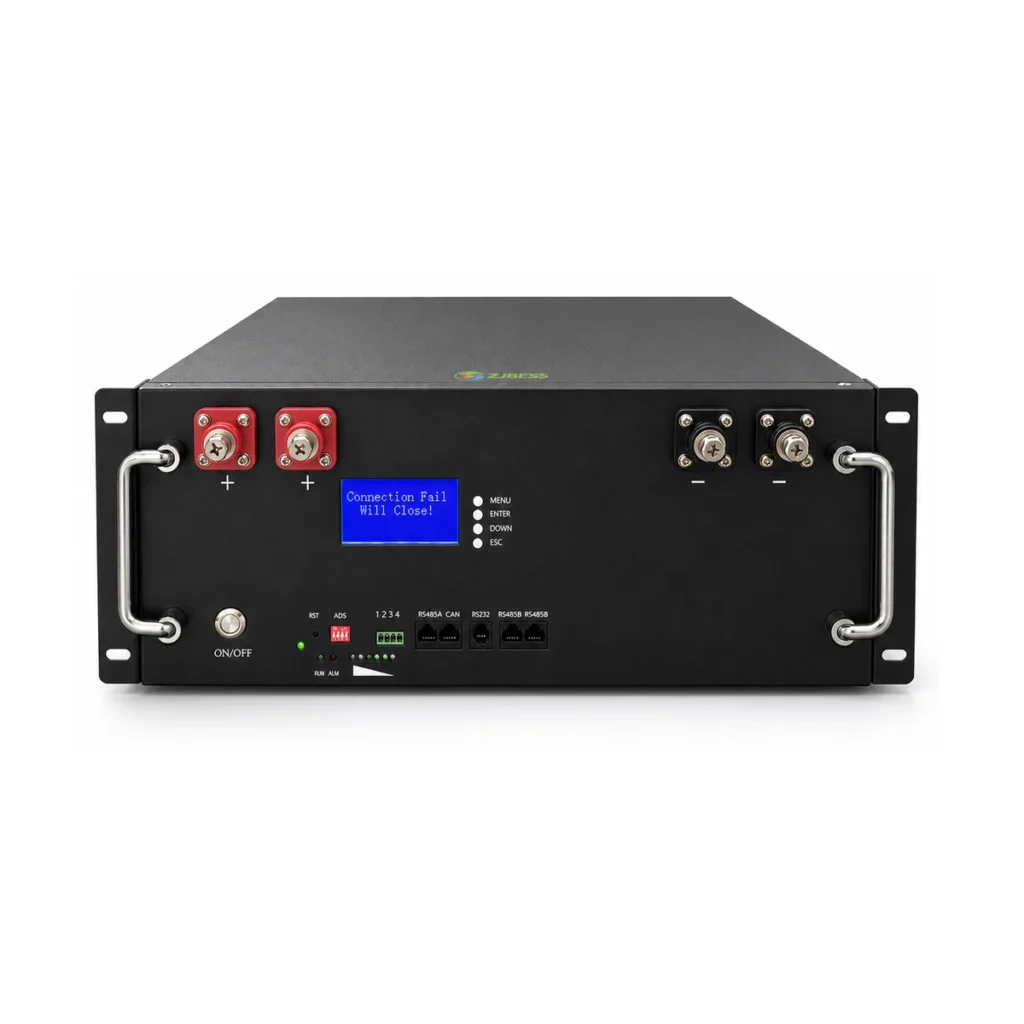
Figure 1. Retained product image from the JJ5KW page. Visible interfaces do not establish rack fit, an approved lifting point or the capacity of a populated cabinet.
This is why a distributor needs the module and support arrangement reviewed together. If shelves or rails carry the load, their suitability cannot be inferred from a rack’s external width. The complete loaded rack, its base and its location then form a further support question. None of the missing ratings can be supplied by counting modules in a photograph.
An accessory choice can change repeat-order suitability. If a later module revision moves a connector, a cabinet that still accepts the enclosure might no longer provide the original cable space. A replacement can therefore fit mechanically yet require a different connection kit. Keep the module revision, compatible supports and supplied cable definitions linked in the stock description.
A common module can make inventory simpler when several approved configurations use it. The benefit weakens if each site needs a different unrecorded rack or cable solution. Compare the approved combinations and their accessory availability before describing a module as a standard replacement for every installation. An empty slot is physical space; it is not an electrical expansion allowance. The battery–inverter compatibility guide handles the separate model, firmware and control questions.
Compare a wall installation with the work needed to remove it
A wall enclosure can leave floor area below it unobstructed, but installation and service still occupy space. The actual unit mass acts through the approved bracket and fixings into the supporting structure. A shipping weight includes packaging-related mass and is not the installed-load value needed for that assessment. A wall finish does not, by itself, identify the structure behind it.
The geometry matters as well as mass. Where an enclosure projects from the wall, its load acts at a distance from the support. The mounting design must account for the actual arrangement. This is an engineering reason to obtain the applicable drawing, not a basis for choosing bolt sizes from a generic battery weight. ZJBESS BG10KW net installation mass and bracket details remain model-document questions; the published gross-weight field must not be relabelled as net mass.

Figure 2. The connection area is part of the layout. The image supplies no cable-bend limit, wall fixing design or removal instruction.
Now consider a change to the finished room. An installer mounts the battery first, then places an inverter, cable enclosure or cupboard nearby. The battery remains visible and its screen is reachable. If the approved removal method needs a lifting or release movement into the new obstruction, the later service job can fail even though everyday operation is possible. A proposal needs to preserve that movement, not merely the view of the front panel.
Manufacturer manuals make these tasks explicit for their own products. The EG4 WallMount 280Ah All Weather manual, version 1.6.3, separates location selection, spacing and bracket installation. Its distances, fixings and methods apply to the named EG4 product; they are not ZJBESS installation values.
For a particular wall site, use the wall-mounted battery installation checklist to assemble the supporting record. The choice in this comparison is narrower: does the proposed wall product have a support and replacement arrangement the site can actually accommodate? If not, a suitable floor or rack arrangement may be worth reviewing even if the wall option initially appears to save more space.
Evaluate floor-standing, low-profile and stacked products on their own terms
An upright floor-standing cabinet can be useful where a suitable wall-hanging solution is unavailable. It still needs an acceptable floor or base, any required restraint and a route for delivery and replacement. Cabinet dimensions do not include every space occupied by packaging, handling equipment or a change of direction through a doorway.
Wheels, where fitted, are a product feature rather than permission to move an operating system. The cables, restraint and prescribed handling method still govern the task. A small installed footprint can coexist with a demanding replacement route. That matters when a distributor compares one cabinet with several modules delivered separately.

Figure 3. The product’s connection side needs access in the installed layout. The view does not approve moving a connected cabinet or using a particular lifting method.
A low-profile product addresses a different constraint: available height. The WS10KW low-profile model belongs in the comparison where its intended orientation and access arrangement suit the site. Low height does not make the enclosure a shelf or permit loads to be placed on it. The confirmed WS10KW net mass is 96kg; that value applies to this named model and does not provide the net mass of a wall or upright cabinet.
A stacked product changes the assembly boundary. For the DD5KW × 3 arrangement, one module’s dimension is not the assembled height including base and control parts. Nor does a picture with three modules establish the maximum physical stack or permitted electrical grouping. A future four-module request needs the actual configuration reviewed rather than an extrapolation from the current picture.
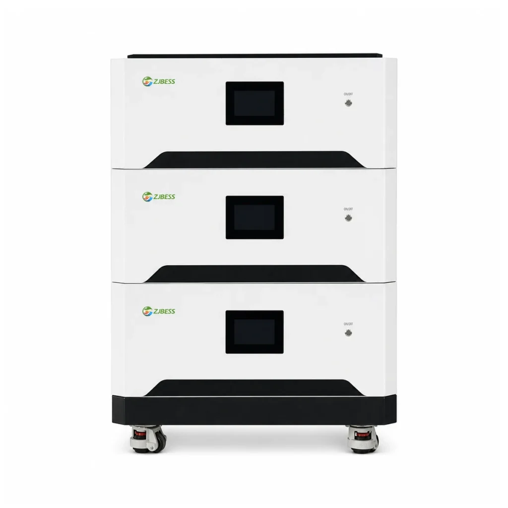
Figure 4. The supplied assembly includes more than a module-height number. No maximum stack height or expansion approval is inferred from this view.
For a stacked arrangement, ask which components must move to replace the affected unit and what shutdown applies to that work. In a product whose service method requires removing upper components first, a lower unit can involve more handling than its own mass suggests. That is a conditional service scenario, not a statement about the approved DD procedure. The model’s service documentation must establish the actual sequence.
Draw the operating space and the removal space separately
Two arrangements can fit inside the same room and still allow different jobs. An enclosure footprint describes where equipment stands. It does not describe an open door, a module moving forward or the space used by people and approved handling equipment. “There is spare floor area” is incomplete unless that area is in the right place for the required movement.
Consider an illustrative rack facing a fixed cupboard. The cabinet fits, and its controls remain accessible. Later service requires a module to move forward before it can be carried away. If the cupboard interrupts that movement, front-panel access has not provided a removal route. Turning the module after it has left its supports may not be an available handling method.

Figure 5. Conceptual paths only, not to scale. The diagram gives no clearance, lifting method or ZJBESS installation instruction.
The useful comparison has three stages. First, the proposed arrangement must support normal operation and permitted access. Next, the named service unit must be removable by the applicable method. Finally, a replacement must be able to reach the same position. A route that works while the room is empty may fail after the remaining equipment is installed.
An upright cabinet might need a turning route that a bare module does not. A wall enclosure might need a release movement that a floor cabinet does not. A modular rack might require a clear forward path even where there is plenty of free space beside it. The relevant direction follows the actual product and task. There is no single universal clearance that can resolve all three cases.
The response to an obstruction can be a changed room layout, a different suitable product or a revised approved support arrangement. It should not be an improvised handling promise. Record the unresolved task in the proposal so that sales, installation and service teams are comparing the same limitation.
Put nominal energy on the same basis before comparing packages
ZJBESS’s published ratings provide a useful arithmetic starting point. The JJ5KW rack module is listed at 51.2V and 100Ah, or 5.12kWh nominal energy. The BG10KW wall model is 51.2V and 200Ah, or 10.24kWh. The LS15KW floor model is 51.2V and 300Ah, or 15.36kWh. The characters KW in a commercial model name do not independently establish AC output power.
| Arithmetic quantity | Nominal energy total | What the comparison establishes |
| Two units each rated 5.12kWh | 10.24kWh | The same nominal-energy sum as one BG10KW |
| Three units each rated 5.12kWh | 15.36kWh | The same nominal-energy sum as one LS15KW |
| One unit rated 15.36kWh | 15.36kWh | A one-unit energy rating, not proof of a complete installed system |

Figure 6. Nominal-energy arithmetic only. The blocks do not specify series or parallel wiring, an approved module count or equal usable AC energy.
The sum is not an approved system. It does not establish equal current capability, conversion losses, usable energy or runtime. It also does not establish equal handling work: three separately supported units and one cabinet remain different physical proposals. For current references, consult the JJ5KW data sheet, BG10KW data sheet and LS15KW data sheet together with the applicable order revision.
Only after confirming each proposed system should the distributor compare its complete supplied package. Modules can require an external rack and interconnections; a cabinet can still exclude an inverter or external protection. A wall product can include a bracket while leaving site-specific fixings to the installer. Those boundaries change the delivered task without changing the nominal kWh printed on the battery.
Use the home battery quote comparison guide for the cost calculation, and the home battery sizing guide where the load and backup requirement are still unresolved. Choosing a mounting format cannot compensate for an energy or simultaneous-power requirement that has not been established.
Separate replaceability from continued operation
When one unit needs replacement, three questions have different answers: can it be reached and removed; what shutdown and isolation apply; and what configuration is permitted to operate afterward? Mechanical access answers the first question. It does not authorize a live disconnection or establish that the remaining equipment can carry the load.
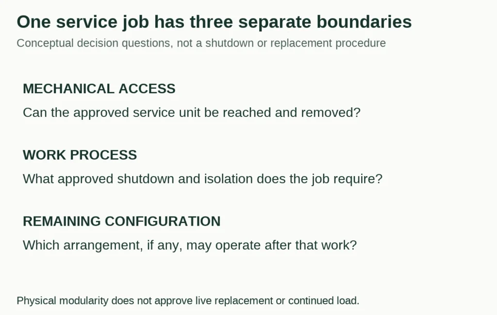
Figure 7. Decision boundaries, not a service procedure. The diagram approves neither live replacement nor uninterrupted operation.
An invented current-sharing example shows why the last question matters. Assume three identical, approved parallel units share a total 180A DC equally at the same voltage. Each then supplies 180 ÷ 3 = 60A. If the system is allowed to operate with two units and the same total current continues, the equal-share value becomes 180 ÷ 2 = 90A per unit, a 50% increase.

Figure 8. Assumed equal sharing and unchanged total current. These are not ZJBESS current ratings or a redundancy approval; actual controls may reduce the load or stop operation.The example makes no hot-swap claim. Actual branch currents can differ, controls can reduce current and a system can require a different minimum configuration. If the two remaining units are not approved for the task, a reduction in load or a shutdown may be necessary under the applicable design. A modular enclosure alone cannot guarantee availability during maintenance.
Discover’s AES manual, section 5.5, illustrates why parallel load sharing depends on the interconnection arrangement for its product. The current-sharing calculation here is a separate engineering illustration; its 180A input is invented and none of that manufacturer’s wiring values is transferred to ZJBESS.
Service planning must also distinguish the remedy from carrying it out. ZJBESS’s confirmed LS15KW policy provides a ten-year warranty with free replacement within its applicable scope. That does not, by itself, allocate local lifting work, return transport or every site expense. The supplier, distributor and installer need the corresponding responsibilities. The approved model revision and connection kit remain relevant when a replacement is dispatched years after the original order.
Turn the format comparison into a defined supply request
A useful enquiry identifies the intended job without asking the buyer to invent engineering values. Send ZJBESS the proposed battery model and quantity, destination, inverter’s complete model and the required load or backup task. Add a description or drawing of the available space and any delivery or service obstruction. The responsible technical source can then identify which installation and configuration documents apply.
For each proposed format, keep the battery and the required supports, connection kit, external equipment and locally supplied items visible in the quotation. Identify the service unit to be replaced and the work that must be planned around it. Where one item remains unknown, retain that limitation beside the affected installation, expansion or availability promise.
ZJBESS has confirmed factory compatibility testing and customer compatibility verification after delivery. Relevant certification and report documents also exist. Those facts support a request for the applicable records; they do not approve every inverter, mounting arrangement or destination. The same model and revision used in the proposal should be identifiable in the evidence supplied.
Standard-model dispatch is stated as 15 working days, with transport separate and the starting milestone and actual schedule agreed with sales. A replacement route into the building and a shipment date are different parts of the plan. Neither can be inferred from the mounting label.
Use ZJBESS distributor support to request current model information, the relevant installation documents and an itemized proposal. Keep the format choice tied to a supported arrangement, a workable delivery and removal route, and an approved system configuration. Those are the conditions that let a distributor turn an attractive enclosure into a product it can supply and support.
Include low-profile and stackable formats in the comparison
Compare at the same target nominal energy and load assumptions. Installation format changes handling, supports, connections and access; it does not by itself establish inverter compatibility or usable AC power.
Rack-mounted
Check rail spacing, usable depth, load-bearing supports and module-removal access. Compare multiple JJ5KW units with a larger JJ model using the full rack, wiring and service scope.
Wall-mounted
Preserve floor space only where the wall, net battery weight, bracket and fixing design are suitable. Obtain the model-specific drawing and lifting/access plan.
Floor-standing
Review cabinet floor loading, delivery turns and maintenance space. For larger cabinets include unloading equipment and a replacement route in the cost comparison.
Low-profile horizontal
Use WS options where restricted height is the defining constraint. Confirm intended horizontal orientation, front access and ventilation; do not treat the enclosure as a shelf.
Stackable
Treat DD5KW × 3 as a matched three-module bank. Obtain dimensions and weight including base/control parts, the maximum physical stack height and the approved expansion grouping.
| Product details | Nominal energy / format | Runtime | Selection check |
|---|---|---|---|
| WS10KW | 10.24kWh Low-Profile | 8.5h | Restricted height, approved horizontal orientation and front service access. |
| BG10KW | 10.24kWh Wall-Mounted | 8.5h | Wall structure, net weight, bracket/fixings and lifting access. |
| LS15KW | 15.36kWh Floor-Standing | 12.7h | Floor-standing installation, target backup load and applicable configuration records. |
| DD5KW*3 | 15.36kWh Stackable | 12.7h | Three-module bank, full assembled height, base and expansion topology. |
| LS20KW | 20.48kWh Floor-Standing | 17.0h | 18/20kWh alternatives, recharge opportunity and cabinet delivery route. |
| LS40KW | 40kWh Floor-Standing | 33.1h | Large-cabinet handling, unloading, isolation and replacement access. |
| JJ5KW | 5.12kWh Rack-Mounted | 4.2h | Rack rail spacing, usable depth, support loading and planned module count. |
Runtime assumes a full starting charge, a 90% discharge window and 92% inverter efficiency. These are calculation assumptions, not measured performance or guaranteed runtime; standby use, temperature and ageing are excluded. Confirm continuous and startup power separately.
To compare delivered cost, include the battery, support/base/rack, cables, protection, inverter, freight, unloading, installation and the agreed service procedure. Several units do not automatically guarantee operation during replacement of one unit.