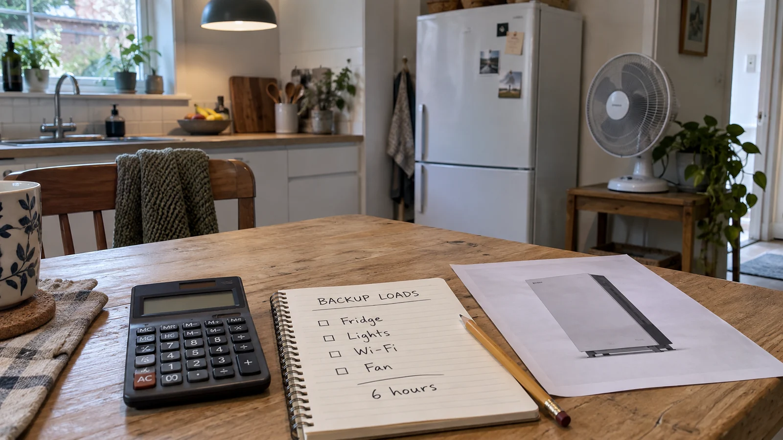
A battery quote that says “15 kWh” leaves an important question unanswered: what needs to keep running, and for how long? A home that needs refrigeration, lighting, and internet during an outage has a different requirement from one that also needs air conditioning or a water pump.
To size a LiFePO4 home battery for backup, calculate the energy used by the selected loads over the outage period. Then, account for the battery energy available at the start of that outage and the losses before it reaches those loads. Check simultaneous power demand separately. The battery, inverter and backup configuration must support both requirements.
The example below follows a six-hour backup brief through those decisions. It is a planning calculation with stated assumptions, not a customer installation or a ZJBESS performance test. It is intended to help installers and buyers prepare a useful specification before requesting a quotation. Distributors can use the same method to define the customer load task behind a proposed stock configuration.
Start with the circuits that need backup
Write down the equipment the household expects to use during an outage. Be specific about heating, cooling, cooking, and pumping. Leaving an electric water heater off the backup circuit can change the required battery size far more than choosing between two similar battery models. A monthly electricity bill helps describe overall consumption, but it does not show which appliances run together or how much energy they need during a particular outage.
For backup sizing, use monitoring data for the selected circuits where available. For appliances that cycle on and off, record energy over a representative period; keep their running and starting power for the separate power check.
For each load, energy in kWh equals average power in kW multiplied by operating hours. The U.S. Department of Energy distinguishes stored energy from power capacity: kWh describes an amount of energy, while kW describes the rate at which it is supplied. A battery needs enough of each for the intended job.
Calculate the energy for a six-hour outage
Suppose a household wants six hours of backup, including one air conditioner. The figures in this table are illustrative inputs. They are not typical appliance ratings and should be replaced with measurements or verified estimates for the actual home.
| Selected load | Assumed average power | Operating time | Energy required |
| Refrigerator and freezer combined | 100 W | 6 h | 0.60 kWh |
| Selected lights | 120 W | 6 h | 0.72 kWh |
| Router and internet equipment | 20 W | 6 h | 0.12 kWh |
| Two fans combined | 120 W | 6 h | 0.72 kWh |
| Computer and monitor | 150 W | 4 h | 0.60 kWh |
| One air conditioner | 900 W | 6 h | 5.40 kWh |
| Total | — | — | 8.16 kWh |
The air conditioner accounts for 5.40 kWh of the 8.16 kWh requirement. Without it, the same brief needs 2.76 kWh. Before comparing battery prices, the buyer therefore has a concrete decision to make: whether cooling must continue throughout the outage, and under what conditions.
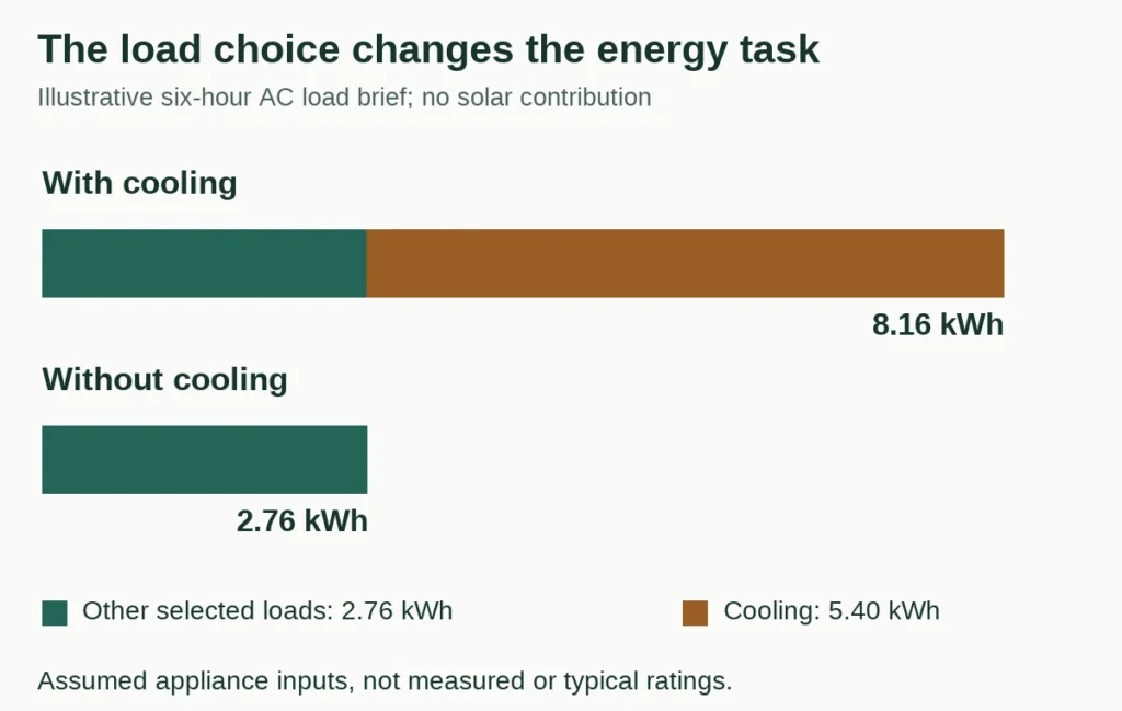
Figure 1. Changing the load brief removes 5.40 kWh from this example; the appliance figures are assumed, not typical ratings.
The 900 W figure is an assumed average electrical input, not cooling capacity or starting power. Actual consumption depends on the equipment, temperature, room and setpoint. A mild-weather reading would be a poor basis for promising summer backup. The refrigerator figure also represents an average over the period, not its compressor starting demand.
This example assumes no solar contribution during the outage. That makes it useful for an evening backup requirement. Daytime solar can be considered separately once the system’s ability to generate and recharge during an outage has been confirmed.
Convert the load requirement into battery capacity
The loads need 8.16 kWh at the AC side of the system. A battery’s nominal energy is a different measurement. For example, the ZJBESS LS15KW product page lists 51.2 V, 300 Ah, and 15.36 kWh nominal energy. Multiplying 51.2 V by 300 Ah gives 15,360 Wh, or 15.36 kWh.
The “15kWh” product label does not establish how much energy will reach the household during an outage. For an initial calculation, assume the battery starts at 90% state of charge, or SOC, and the permitted backup cutoff is 10%. That leaves an 80-percentage-point window. Also assume a 90% efficiency for the discharge path to the AC loads.
These percentages are calculation assumptions, not LS15KW specifications or recommended settings. Here, SOC is treated as a proportion of nominal energy; confirm how the proposed system defines and displays SOC before applying this calculation to a product.
Required nominal battery energy = 8.16 kWh / [(0.90 – 0.10) * 0.90] = approximately 11.33 kWh.
This is a preliminary energy requirement before auxiliary consumption, temperature effects, ageing and project-specific design allowance. The installer should use documented system data to account for those factors. A universal margin cannot replace that review.
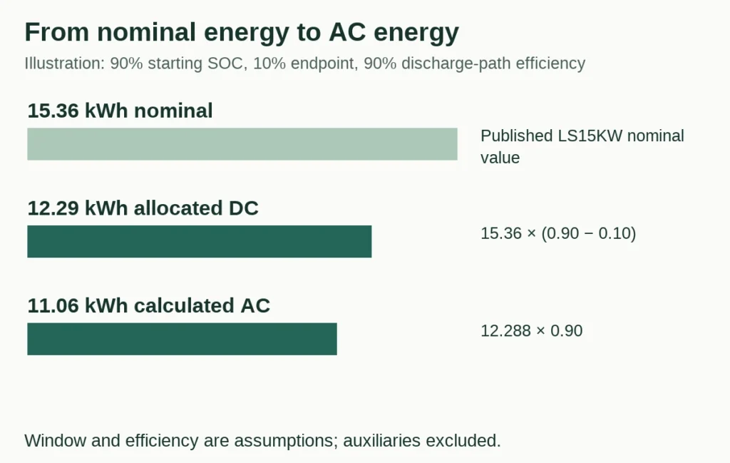
Figure 2. Keep the measurement boundary visible. The nominal energy is a published LS15KW value; the discharge window, efficiency and calculated outputs are illustrative.
Using 15.36 kWh as a nominal capacity for illustration shows why the starting charge matters. The following table holds the 10% cutoff and 90% discharge-path efficiency constant.
| SOC when the outage begins | Calculated AC energy before auxiliary use | Compared with the 8.16 kWh load target |
| 100% | 12.44 kWh | 4.28 kWh above target |
| 90% | 11.06 kWh | 2.90 kWh above target |
| 60% | 6.91 kWh | 1.25 kWh below target |
These are arithmetic results, not measured LS15KW outputs. At the assumed 60% starting SOC, this capacity would fall short even before the system’s own energy use is considered. A larger battery alone does not establish reliable backup; the charging schedule and reserve policy also have to make energy available when it is needed.

Figure 3. The same nominal capacity crosses from above to below the energy target when only starting SOC changes. The cutoff is held at 10% and assumed discharge-path efficiency at 90%.
Read the definitions in a supplier’s datasheet before adjusting its capacity figure. If “usable energy” already accounts for the permitted discharge window, do not subtract that window again. If the energy is specified at the AC output, check which conversion losses are already included. Also distinguish one-way discharge efficiency from round-trip efficiency, which covers charging and discharging. Tesla’s Powerwall 2 AC specifications, for example, state separate total and usable energy values and define the round-trip measurement path and test conditions. Those values apply to that product, not to ZJBESS batteries.
Keep reserve policy separate from the outage endpoint
A reserve setting needs the same care. Energy reserved during normal grid operation may become available during an outage. For the backup calculation, establish the expected starting SOC and the cutoff that actually applies in backup mode; do not add a second reserve deduction without checking what the setting means. Tesla’s Backup Reserve explanation is a concrete example: its reserved energy becomes available during an outage. This explains why the two concepts differ; it does not define a ZJBESS setting.
For example, if an installer has already used a 90% starting SOC and 10% outage endpoint, the model has allocated an 80-percentage-point window. Subtracting another 20 percentage points simply because an app also displays a 20% reserve would change that window to 60 percentage points. That second deduction is justified only if it represents an additional restriction that really applies during backup. Resolve the operating policy first, then calculate once.
Compare two capacities against one timed load task
Consider a separate, smaller backup brief: 0.25 kW for the first four hours, followed by 0.50 kW for another four hours. These are aggregate average AC loads for two successive periods, not two loads running throughout the full eight hours. Their energy demand is (0.25 × 4) + (0.50 × 4) = 3.00 kWh. Keeping the time blocks visible prevents the second-period demand from being overlooked.
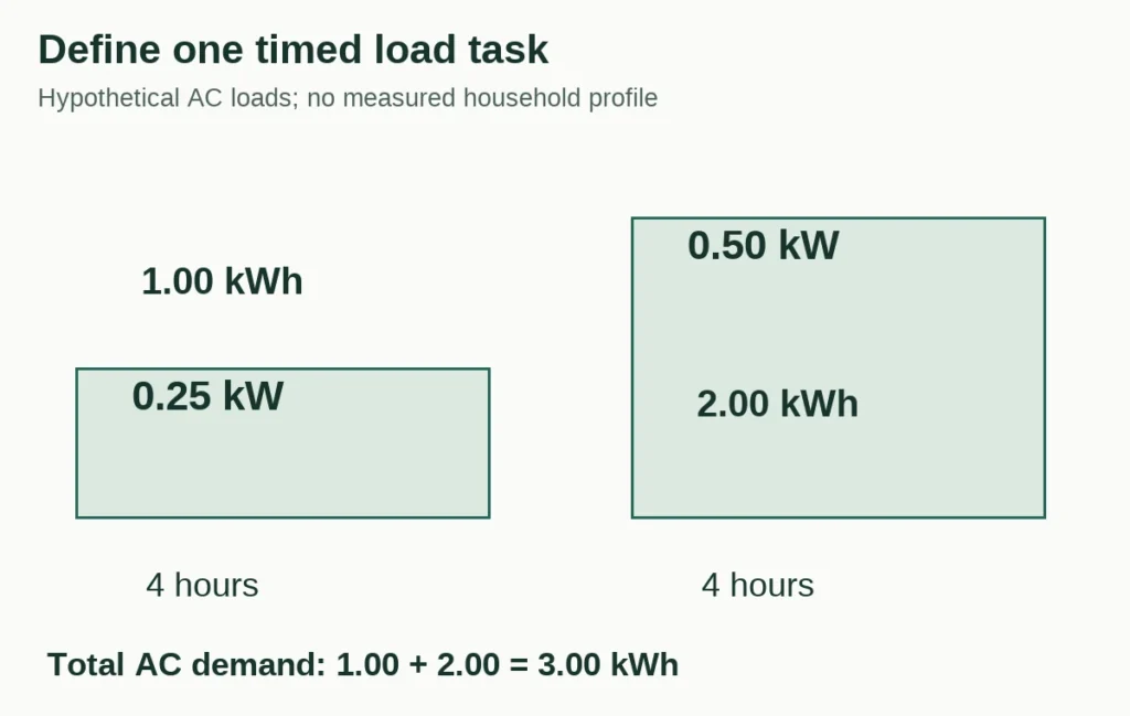
Figure 4. A separate eight-hour hypothetical task. This does not replace the six-hour, 8.16 kWh example above.
Compare 10.24 and 15.36 kWh of nominal energy against this same task. For this example only, assume an outage endpoint of 20% SOC and a combined discharge-path factor of 90%. Treat SOC on the same simplified nominal-energy basis for both capacities, with no solar recharge, auxiliary consumption or other limiting condition. These are model inputs, not approved settings or measured usable energy for BG10KW or LS15KW.
Calculated AC allocation = nominal energy × (starting SOC − ending SOC) × assumed discharge-path factor.
| Starting SOC | 10.24 kWh nominal | 15.36 kWh nominal | Compared with the 3.00 kWh task |
| 80% | 5.53 kWh | 8.29 kWh | Both exceed the energy target before excluded effects |
| 50% | 2.76 kWh | 4.15 kWh | Smaller allocation falls short by about 0.24 kWh |
The 50% row is the useful crossover. The smaller capacity still contains energy, but its allocated window does not cover this task. The larger capacity provides more energy within the same percentage window. At 80% starting SOC, however, the smaller capacity also clears the task’s energy target. Choosing the larger option therefore needs a reason such as the expected starting charge, a longer load task or a documented allowance; nominal capacity alone does not make that decision.

Figure 5. Hypothetical comparison with a 20% ending SOC and 90% discharge-path factor. The lower bar is 2.7648 kWh before rounding, leaving a 0.2352 kWh shortfall.
Use the crossover to improve the project brief
The same simplified relationship can be rearranged: required starting SOC = ending SOC + AC task energy ÷ (nominal energy × assumed discharge-path factor). For this task, the mathematical starting values are about 52.6% for 10.24 kWh and 41.7% for 15.36 kWh. They are model thresholds before excluded effects, not recommended reserve settings or guaranteed backup thresholds. Actual SOC estimation, temperature, battery condition and system behaviour require applicable evidence.
This calculation turns “bigger is safer” into a more specific question: can the charging schedule make enough energy available before the expected outage? If the system repeatedly begins below the required window, the choices include reducing or scheduling loads, improving an approved recharge opportunity, or changing capacity. Each addresses a different constraint. Adding nominal kWh does not create a charging source.
The highest average demand in this timed example is only 0.50 kW. That still leaves a separate question about simultaneous and starting power: an average over four hours can hide a short, much larger demand. An energy allocation above 3.00 kWh cannot approve those events.
Check the power the system must deliver at once
The load table estimates energy. Its average values cannot size the inverter or establish whether a compressor will start. Build a second record of simultaneous running demand and the starting requirements of motors, pumps and air conditioners, including how long a starting surge lasts.
Consider a separate power-check example: the selected circuits can require 5 kW at once. At a battery operating voltage of 48 V and an assumed conversion efficiency of 92%, the approximate battery current is:
Estimated battery current = 5,000 W / (48 V * 0.92) = approximately 113.2 A.
A hypothetical battery limited to 100 A continuous discharge could not sustain that operating point, even if its stored energy were sufficient. At the same assumed voltage and efficiency, 100 A corresponds to about 4.42 kW at the AC side before any additional constraints. These are generic examples, not the LS15KW current rating.

Figure 6. An energy surplus cannot remove a current limit. Voltage, efficiency and the 100 A limit are illustrative inputs, not ZJBESS operating permissions.
Check the battery’s continuous and short-duration discharge limits, the inverter’s backup output rating, and any restrictions from the battery management system. The installer must also account for the DC connection and protection equipment. Use the relevant operating voltage and conditions; nominal voltage alone does not describe the whole discharge period.
Adding battery modules can increase available energy, but the existing inverter may still limit AC output. Expansion should be checked against the approved configuration, including module combinations and current sharing. The battery and inverter compatibility guide covers the model, firmware, protocol and current review in more detail.
Confirm inverter compatibility and outage operation
A matching voltage range and a CAN or RS485 port are starting points for an integration check. Ask for confirmation covering the exact battery and inverter models, firmware, communication configuration and permitted module arrangement. Victron’s published BYD integration guide illustrates the level of detail involved: it specifies communication hardware, firmware requirements and minimum battery configurations. It is an example of documented integration, not evidence that a ZJBESS battery supports that pairing.
Backup operation needs its own confirmation. Identify which circuits and phases will remain powered, what equipment provides the required grid isolation and transfer, and whether the inverter can supply those circuits when the grid is absent. If a load cannot tolerate an interruption, check the documented transfer performance against that requirement.
Also establish what the solar system does during the outage. The Australian Government’s Solar Consumer Guide explains that battery backup depends on configuration: some arrangements supply loads from the battery while the solar inverter shuts down; others can continue using solar after isolating from the grid.
Check whether energy can be restored before the next outage
For a home with repeated outages, check the recharge window as well. Restoring 8 kWh of stored energy at a sustained net storage rate of 2 kW would take four hours. If the quoted 2 kW is measured before losses, or charging is interrupted or limited, allow more time. The solar array’s nameplate power is not a promise of power available to recharge the battery after household demand is supplied.

Figure 7. Net stored power is after concurrent demand and charging losses. The two sustained rates are assumed, not charger or solar ratings.
With only six hours available, a sustained net rate of 1 kW would restore 6 kWh, leaving a 2 kWh deficit against that 8 kWh replenishment task. Doubling the cabinet capacity would not change this input-energy deficit. Use the permitted charge current, the actual charging period and the source energy remaining after household use to decide whether a proposed capacity can be replenished.
Choose the format after the electrical requirements are clear
The enclosure affects access, placement and maintenance. Wall mounting needs a suitable structure; floor-standing units need space, a suitable support surface and a workable delivery route. Rack and stackable arrangements need the approved module layout and service access. Confirm the installation environment and clearances from the relevant documentation. ZJBESS offers several home battery formats. A floor-standing model and a stackable model can serve different physical layouts, but their appearance does not prove electrical interchangeability.
For the main ZJBESS options, compare the BG10KW wall-mounted battery at 10.24 kWh nominal, the LS15KW floor-standing battery at 15.36 kWh nominal, and the LS20KW floor-standing battery at 20.48 kWh nominal. These published energy values identify capacity options, not a kW output or approval for a particular installation. Compare the exact configuration against the load brief, inverter requirements and installation conditions.
Prepare a brief that can be quoted and checked
The six-hour example now has a useful starting specification: 8.16 kWh required by the selected AC loads, an assumed 90% starting SOC, a 10% cutoff and a preliminary nominal energy requirement of 11.33 kWh under the stated efficiency assumption. Simultaneous demand and starting loads still need their own verified figures. This is substantially more useful to a supplier than a request for “a 15 kWh battery.”
For a ZJBESS configuration review, include:
- The destination country, grid voltage and phase arrangement.
- The selected backup loads, their energy use, simultaneous running demand and any starting loads.
- The required backup duration, expected starting charge and frequency of outages.
- The inverter’s full model number and firmware, plus details of existing solar and any generator.
- The available installation space, temperature conditions, quantity and planned expansion.
Ask the quotation to identify the proposed battery configuration, the capacity definition used, the supported inverter arrangement and any limits that affect the brief. Where the proposed system cannot meet a load or duration requirement, that exception should be visible before an order is placed. For a first sample, the sample acceptance test record guide explains how to retain the conditions and measurement boundary behind an observed result.
Send your backup requirements to ZJBESS with the load record and inverter details. For distributor quantities, use ZJBESS distributor support to keep the load brief, configuration, documents and order scope together. The supplier or responsible engineer should identify the approved limits and unresolved technical items; buyers do not need to guess them.
Existing model comparison retained separately
The live page appends the seven-model comparison through the site template. It is preserved in this update and omitted from the replacement body to prevent duplication. The local preview includes the unchanged block. Keep its full-charge 90 percent discharge-window and 92 percent inverter-efficiency assumptions separate from the examples in this article.
Compare current ZJBESS home battery options on one basis
Required nominal battery energy = essential AC load × target hours ÷ assumed discharge window ÷ assumed inverter efficiency. For example, 1kW × 8h ÷ 0.90 ÷ 0.92 ≈ 9.66kWh. Use actual consumption and permitted settings for the final design.
| Product details | Nominal energy / format | Runtime | Selection check |
|---|---|---|---|
| WS10KW | 10.24kWh Low-Profile | 8.5h | Restricted height, approved horizontal orientation and front service access. |
| BG10KW | 10.24kWh Wall-Mounted | 8.5h | Wall structure, net weight, bracket/fixings and lifting access. |
| LS15KW | 15.36kWh Floor-Standing | 12.7h | Floor-standing installation, target backup load and applicable configuration records. |
| DD5KW*3 | 15.36kWh Stackable | 12.7h | Three-module bank, full assembled height, base and expansion topology. |
| LS20KW | 20.48kWh Floor-Standing | 17.0h | 18/20kWh alternatives, recharge opportunity and cabinet delivery route. |
| LS40KW | 40kWh Floor-Standing | 33.1h | Large-cabinet handling, unloading, isolation and replacement access. |
| JJ5KW | 5.12kWh Rack-Mounted | 4.2h | Rack rail spacing, usable depth, support loading and planned module count. |
Runtime assumes a full starting charge, a 90% discharge window and 92% inverter efficiency. These are calculation assumptions, not measured performance or guaranteed runtime; standby use, temperature and ageing are excluded. Confirm continuous and startup power separately.
The main product page opens from each model. Its variant table contains the exact energy options; select the final battery only after checking continuous/startup power, installation and inverter settings.
Check the next recharge before adding capacity
List the energy that must be replaced between outages. Compare it with permitted charging power and the hours available, allowing for charging stages, losses, variable solar and loads running at the same time. More stored energy helps only when the system can replenish the energy it uses.