
A supplier answers “yes, compatible”, but the distributor still needs to know what that means after installation. Will the inverter receive the battery’s state of charge? Will it respect changing charge limits? Can the combination support the promised backup loads?
To check LiFePO4 battery inverter compatibility, compare the operating voltage ranges and current limits, confirm the exact BMS communication profile, and obtain approved charge and protection settings. Then verify the combination in the operating modes you intend to sell. Matching voltage labels or communication sockets alone does not establish a working system.
This guide is for distributors evaluating 48V-class home storage systems before quoting a configuration. It covers the documents and acceptance checks to request; the manufacturer’s instructions for the exact equipment govern installation.
Check four parts of the battery and inverter pairing
| Layer | The question it answers | Typical failure when it is wrong |
| DC voltage window | Does the battery’s voltage range sit inside what the inverter accepts? | Inverter will not start, or shuts down early in discharge |
| Current limits | Can the battery supply and accept what the inverter will demand? | BMS protection trips under load, or charge is refused |
| Communication protocol | Can the two devices exchange usable data? | No state of charge, no coordinated limits, alarms |
| Charge parameters | Are voltage, current and temperature settings approved? | Overcharge protection events, or persistent undercharge |
Ask the supplier to distinguish a specification comparison from a documented integration and an observed test. Each provides different evidence. A specification match is a useful first filter, but it does not show that the selected firmware, settings and operating mode work together.

Four checks screen a pairing; document review, sample evidence and a site record establish different scopes.
Compare operating voltage ranges and startup requirements
For LiFePO4 products, “48V” often describes a system class. Sixteen nominal 3.2V cells in series give 51.2V nominal; fifteen give 48V nominal. Confirm the actual pack specification rather than assuming every 48V-labelled battery has the same cell count. Nominal voltage is a label for comparison, not a substitute for the full operating window.
ZJBESS’s LS15KW floor-standing battery is one concrete example. Its published values are 51.2V nominal, 300Ah, 15.36kWh, with a recommended charge current of ≤100A and a maximum continuous discharge current of ≤200A in its published specification sheet. Treat those as figures to check against the current specification sheet for the revision you are quoting, not as evidence about any particular inverter.
Compare these items in the two specification sheets:
- The battery’s full voltage range across its charge and discharge cycle, not only the nominal figure. A pack that is nominally 51.2V operates meaningfully above and below that.
- The inverter’s battery input range and any separate startup, restart or battery wake-up requirements. Use the battery-input specifications, not the PV input or MPPT voltage range.
- The cell count and approved charge settings. A 15S pack and a 16S pack can both be sold in the 48V class, but their settings are not interchangeable. Do not mix them in a bank unless the manufacturers explicitly approve the arrangement.
Convert the inverter’s power rating into DC current
Start with the AC load the battery must actually support. For an initial screening calculation, convert that power to DC current using a working battery voltage and inverter efficiency. Also check the inverter’s published maximum battery current, its battery-only output rating and any required minimum battery configuration.
Inverter output power ÷ (DC working voltage × conversion efficiency) = approximate DC current
For a 5,000W load at an assumed 48V working voltage and 92% efficiency:
5,000 ÷ (48 × 0.92) ≈ 113A
The estimate is below the LS15KW’s stated maximum continuous discharge figure of ≤200A, but it does not establish a suitable pairing. Battery voltage falls during discharge, and the permitted current may change with temperature, state of charge or protection settings. The inverter, cables, connectors and protective devices also impose limits. Here, 48V and 92% are illustrative assumptions, not measured ZJBESS results.
The voltage used in that estimate changes the result even when the load does not. The following comparison holds the load at 5,000W and efficiency at an assumed 92%. It does not model temperature derating, cable voltage drop or inverter self-consumption separately.
| Assumed DC working voltage | Calculated battery current | What changes |
| 51.2V | 106A | Higher illustrative working voltage |
| 48V | 113A | About 7A more for the same AC load |
| 44V | 124A | About 17% more current than at 51.2V |
All three voltages are hypothetical calculation inputs. In particular, 44V is not a recommended cutoff or permission to operate a ZJBESS battery at that voltage. Check the approved operating window and the permitted current at the lowest voltage relevant to the promised load. A design that only works at nominal voltage needs a narrower load promise or a documented configuration change.
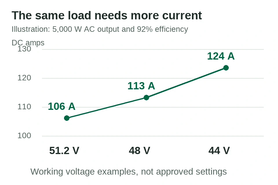
Illustrative current = 5,000 ÷ (working voltage × 0.92). These are calculation inputs, not ZJBESS settings or measured results.
Ask separately about load starting and equipment startup. Motors may require a brief surge above their running power; the inverter’s own DC input can also have an inrush requirement. Request the permitted peak current, duration, test conditions and any required precharge or startup sequence. A peak figure without a duration is not enough to approve the configuration.
For charging, compare the total possible battery charge current from all enabled sources, including solar and AC charging where they can operate together. The LS15KW’s ≤100A figure is labelled recommended charge current. It does not state the absolute maximum or the BMS trip threshold. Ask for the approved setting, any temperature-dependent limits and the applicable warranty conditions before offering a faster charging claim.
For a separate arithmetic example, assume two chargers can operate simultaneously and deliver 60A and 50A at the battery side. Their combined demand is 110A. If the manufacturers have approved a hypothetical 100A total charge limit for that configuration, control must keep the combined current within that limit. The example does not identify a ZJBESS BMS threshold. Where an inverter already reports total battery charging current, do not add its PV and AC input figures again; first establish what each reported value includes.

This arithmetic example assumes both sources can run together. The 100A total limit is hypothetical, not an approved ZJBESS setting or BMS trip threshold.
For a parallel bank, confirm the permitted models, module count, firmware, wiring arrangement and current-sharing conditions. Ask what happens if one module goes offline: the remaining bank must either support the load within its limits or trigger an agreed reduction or shutdown. Adding nominal amp-hours does not by itself establish the bank’s usable power.
Treat the protocol as separate from the connector

The drawing separates connection, application messages and supported versions. It is not a cable pinout or installation diagram.
A matching socket proves very little. RS485 specifies electrical signalling; CAN also defines communication at the data-link level. Neither label alone identifies the battery message format that the inverter expects. The devices still need matching application protocols, settings and wiring. An RJ45-shaped socket does not make an ordinary network cable the correct BMS cable.
The LS15KW specification lists CAN/RS485/232 communication. That identifies available interfaces, not compatibility with every inverter that has one of those ports. Request confirmation for the exact battery revision, inverter model and firmware combination.
Victron’s Pylontech integration instructions illustrate the detail to expect: specified battery models, firmware, different cable types and GX configuration. These instructions apply to the named Pylontech combinations; they are not proof of ZJBESS compatibility and their settings should not be copied into a ZJBESS installation.
Ask for six things in writing:
- The full inverter model and hardware revision, not the brand.
- The protocol or battery profile to select on the inverter, and where that setting lives.
- Firmware versions on both devices that the confirmation applies to.
- Cable specification and pinout, required termination and communication speed, including whether a standard patch cable is approved.
- The required controller or gateway, if any; the communication master and addressing method for a multi-battery bank.
- The document or validation record covering this exact combination.
Keep the written answer with the quotation. A brand logo cannot identify which model, firmware or configuration the supplier has checked.
Decide between closed-loop and open-loop before installation
Closed-loop operation uses a supported communication link to exchange battery information and control limits. Open-loop operation uses approved settings without that full exchange. Some equipment supports both; other combinations require communication. A failed BMS connection should not be treated as permission to switch to open-loop operation.
In a supported closed-loop system, the BMS can report state of charge and communicate charge or discharge limits. Confirm which values the inverter actually uses in each mode. Open-loop systems commonly rely on configured voltage and current limits; state of charge may come from an inverter calculation or a separate battery monitor. Lack of a digital BMS link does not mean every system lacks advance protection. Some designs use separate enable, disconnect or alarm signals, as shown in Victron’s BMS selection guide.
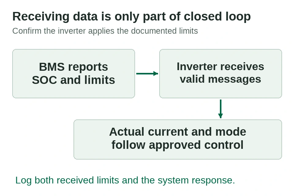
A connected status shows receipt, while logs of limits and the corresponding system response provide evidence of control. Supported behaviour depends on the equipment and mode.
If open-loop is proposed, obtain the approved charging profile, current limit, low-voltage cutoff and restart settings. Include absorption and float behaviour, temperature compensation and equalization settings where the inverter offers them. Confirm support with both manufacturers and ask how the configuration affects monitoring and warranty coverage. A BMS protection trip should not be the routine charging or discharge control method.
The LS15KW sheet lists charging at 0–60°C and discharging at -30–60°C. Those different windows matter when quoting a cold site. Confirm which sensor and device enforce the charging restriction, how charging is reduced or blocked, and the restart conditions. If heating is proposed, obtain the specification for that option; do not assume it is fitted. A discharge temperature rating does not authorize charging at the same temperature.
Verify monitoring and fault behaviour in the intended modes
Before the first order, agree on a commissioning record with the supplier and installer. Record the actual equipment and firmware, initial state of charge, temperature, settings, loads, measured results and pass criteria. The following are acceptance checks to agree for that combination, not a request to provoke protective faults on site.
Check where displayed state of charge comes from, which limits arrive from the BMS, and which settings remain manual. Confirm that charge and discharge control responds as documented. Save the relevant screenshots or logs with the settings record; a battery icon or a “connected” message alone does not demonstrate that the inverter follows the limits.
Also ask for the documented response to lost communication: whether charging or discharging stops, which alarm appears, whether any fallback is approved, and how the system recovers. Any validation should follow the manufacturer’s approved procedure. Do not unplug live connections or force overcurrent, overvoltage or temperature faults to improvise a test.
For backup applications, verify grid-connected and outage operation separately. Check transfer behaviour, the planned load steps, solar charging during an outage, low-battery shutdown and recovery. These depend on the complete system, including the inverter and PV arrangement. Victron’s Pylontech integration guide, for example, distinguishes how discharge limits are handled on-grid and off-grid. A communication check performed with grid support does not establish the promised backup performance.
Use the planned modes to define what the evidence needs to show. A completed grid-connected check leaves the outage row open until it has its own applicable evidence.
| Intended mode or event | Evidence to request | Decision the record supports |
| Grid-assisted operation | Actual battery current, received limits and contribution from the grid | Whether observed performance depended on grid support |
| Battery-only backup | Defined load, working voltage, temperature, duration and control logs | Whether this tested configuration supports that load under those conditions |
| Shutdown and restart | Approved trigger and recovery procedure, alarms and settings record | Whether recovery follows the documented behaviour |
| Communication unavailable | Manufacturer-approved response and any validated fallback scope | Whether the proposed sales promise remains supported when data is lost |
Agree the criteria and responsible technical party before testing. These rows define a record, not instructions to disconnect equipment or force a fault. Leave an untested row marked “not verified” instead of treating another mode as a substitute. If state-of-charge interpretation is the unresolved issue, use the separate battery state-of-charge guide; a displayed percentage alone does not establish current capability or backup duration.
Keep one compatibility record per pairing
Use a separate record for each approved combination. Distinguish “documents reviewed”, “sample validated” and “site commissioned” so a sales quotation does not imply a test that has not happened.
Review the record when a model, firmware version, battery count or installation arrangement changes. Ask the supplier whether the existing approval still applies and what needs revalidation. Keep the previous record so service staff can identify the configuration actually supplied.

Keep the old record with the equipment supplied. A change triggers a scope review; it does not automatically invalidate all previous evidence.
Compatibility with one inverter model does not extend to the brand’s other families. The compatibility record also needs a separate load and energy brief: communication alone cannot establish backup runtime. Use the home battery sizing guide to separate energy and runtime from this power and integration check.
The request fields below can be copied into a supplier enquiry. Distributors can provide the equipment names, quantities and intended loads. The supplier or commissioning engineer should complete the protocol, approved settings and validation fields. Leave unknown values blank and keep the supplier’s response with its document revision. A blank request is not a compatibility certificate.
| Request field | Details to supply or obtain |
| Battery identity | Model, hardware revision, firmware and quantity |
| Inverter identity | Full model, hardware revision and firmware |
| Intended use | Grid-assisted or battery-only mode, backup load and destination market |
| Communication | Protocol/profile, controller, approved cable reference and addressing |
| Approved limits | Source revision for operating voltage, startup and restart settings, recommended versus maximum charge current, continuous discharge and peak current with duration, and temperature limits |
| Evidence | Record identifier, date, conditions, results and unresolved items |
| Scope and responsibility | Documents reviewed / sample validated / site commissioned, approving contact and date |
This information can separate a request that is ready for technical review from one missing a model or firmware version. It cannot turn a brand-level compatibility statement into approval. Approval must come from documentation for the equipment and configuration being supplied.
Match a Lithium Battery to Your Inverter in Nigeria
Send the inverter model, firmware and battery input voltage before ordering. Two inverters with the same kVA can use different battery voltages, have different continuous kW ratings or need different BMS settings. Read both the VA and W ratings from the nameplate or manual.
Example: A 5kVA unit supplying 4kW at a 0.8 load power factor draws about 87A from a 51.2V battery at 90% inverter efficiency. A two-hour target at an 80% usable battery fraction needs about 11.1kWh nominal. Check the inverter’s continuous real-power limit, the battery current at low voltage and the surge duration before choosing a configuration.
Use the home battery and inverter comparison to shortlist equipment, then ask the supplier to confirm the exact pairing. For commissioning, request a signed record of the approved wiring and protection, BMS communication, charge source, charge readings and alarm checks. The installer should verify the result against the equipment manuals.
Check the Connection and Verify Battery Charging
Before installation. Give the installer the battery and inverter manuals for the exact models and revisions. Ask for the approved DC connection and protection drawing, the battery voltage and current limits, and the BMS interface, cable pinout and selected profile. The installer should verify polarity, protection, isolation and grounding against the manuals before commissioning. Record the manuals and configuration used.
During the charge test. With an enabled charging source and a battery that can accept charge, record the selected source, charge status and current direction at the battery using the approved monitor. Check the BMS charge permission, any alarms and the applicable charge limit. A source icon or an AC input reading alone does not show that current is entering the battery. If battery current stays near zero, have the installer check charge schedules, available input, temperature, state of charge and BMS limits before changing settings. See the Victron BMS commissioning example for the general principle of verifying current on the battery side.
Send a complete compatibility request before quoting
Where a material point remains unconfirmed, make it an open item in the quotation. State whether the proposal is subject to model approval, a sample check or a defined commissioning test. Agree who will supply the cable, configure the equipment and handle a compatibility-related support request.
To discuss a ZJBESS pairing, start with the battery model and quantity, inverter make and full model, intended backup loads and destination market through the ZJBESS contact page. Include firmware versions and charging requirements if available; ask the supplier to identify any missing technical details. Request the current specification sheet and the documentation available for that exact combination. The reply should identify what is confirmed and what still needs checking before you commit to a customer.
For a distributor procurement review, the ZJBESS distributor support page provides the commercial enquiry route. Send the pairing record with the model request so the technical and supply questions refer to the same configuration.
Request a model-specific ZJBESS configuration record
Provide the battery model and hardware/BMS version, inverter model/firmware, communication method, quantity and intended backup mode. Request a record identifying the tested settings, charging/discharging, communication and backup functions, test conditions/date and limits.
ZJBESS has tested inverter combinations; sales must confirm whether a record applies to the exact combination you propose. This guide does not publish a verified model/firmware matrix. Repeat the review when hardware, firmware or topology changes.
Choose the battery model or prepare a sample acceptance review.