

An existing solar system does not need the same storage proposal as a new installation. With AC-coupled storage, a suitable existing PV inverter can remain in service while separate battery conversion equipment is added. With DC-coupled storage, solar can charge a battery through a compatible DC path, which may require a different inverter or charging arrangement. Neither label establishes backup operation or approves a particular battery pairing. For distributors and installers, the useful comparison is the work each proposal must accomplish: retain suitable equipment, capture the available surplus, supply the intended loads and behave correctly when the grid is unavailable. A difference in conversion losses matters, but it is only one part of that decision. Understanding the options available for ac vs dc coupled battery storage is crucial.

Identify where the solar and battery paths meet
When considering energy storage solutions, the choice between ac vs dc coupled battery storage can significantly impact performance and efficiency.
In a common AC-coupled retrofit, the PV inverter converts the panels’ DC output to AC. Solar can supply simultaneous AC loads, and a battery inverter/charger can convert available AC energy back to DC for charging. Later, the battery’s DC output is converted to AC for the loads. The coupling label describes where those functions connect; it does not mean a bare battery accepts AC.
In a DC-coupled arrangement, solar and storage share a compatible DC-side route. A hybrid inverter may combine PV conversion and battery conversion functions in one enclosure. Other designs use separate DC charging equipment. Count functional stages rather than assuming that each stage must be a separate box. The Australian Government’s inverter explanation distinguishes the common AC retrofit and hybrid DC arrangements.

Figure 1. Functional energy routes, not a wiring diagram. Equipment, protection and device pairing must be defined for the project.
A hybrid inverter can also have an approved role in an AC-connected arrangement. Consequently, “hybrid” in a product name does not fully describe how an existing PV system will connect. A proposal should show which equipment receives the original PV output and which equipment controls battery charging. SMA’s retrofit explanation describes both replacement and separate battery-inverter approaches within its own product range; its named combinations are not approvals for ZJBESS batteries.
This distinction prevents a common specification error. The battery input and the PV input are different interfaces, even when both are DC. Do not infer permission to connect a battery to an MPPT input, or to reconnect an AC-output PV device to a DC battery path. The drawings here explain functions; the equipment manufacturers and responsible designer determine the actual connections.
Decide what can remain before comparing new equipment
Begin with the full existing inverter model, its operating condition and the system layout. “Already has solar” leaves several materially different starting points open.
| Existing arrangement | Route worth reviewing | What could change the decision |
| Suitable solar-only inverter | Retain PV conversion and assess separate AC-connected storage | Required operating modes, control interface, metering and connection approval |
| Battery-ready or hybrid inverter | Assess its approved battery input and supported configurations | Exact model, firmware, battery list, activation requirements and backup equipment |
| Inverter already due for replacement | Compare a replacement hybrid proposal with an AC addition | Remaining equipment life, PV input compatibility, complete cost and outage scope |
| PV system with microinverters | Start from the existing AC-output solar arrangement | Supported AC integration and outage control; a DC proposal may involve wider changes |
Keeping a working PV inverter can avoid replacing a useful component. That benefit should be compared with the equipment and work needed for the battery addition, rather than assuming the cheapest battery makes the cheapest retrofit. Conversely, replacement is not automatically wasteful if the original inverter is unsuitable for the planned task or already needs replacing.

Figure 2. The starting equipment changes the scope. These are review routes, not approvals for the illustrated arrangements.
For example, consider an otherwise serviceable solar-only inverter at a home seeking evening self-consumption. An AC storage proposal may preserve its ordinary PV role. If the customer also expects that PV inverter to keep producing through an outage, that is an additional integration task. The first benefit does not establish the second.
A battery-ready label also needs interpretation. It may describe hardware capability while leaving battery compatibility, software, controls or backup accessories unresolved. Ask what the exact product supports in the proposed operating mode. The battery and inverter compatibility guide covers voltage, current, communication and the model-specific evidence; this article addresses the architecture around that pairing.
Compare losses for the same energy task
A direct daytime load and an evening load use different routes. Solar used immediately on the AC side does not have to complete a battery charge and discharge cycle. Applying a battery round-trip figure to all solar generation therefore overstates the energy passing through storage.
For a stored-energy comparison, define the same input and output boundaries. The following arithmetic starts with 8.00kWh at the PV DC output allocated entirely to storage, and ends at the AC load after later discharge. It assumes adequate charging time and storage headroom, no clipping, and no power limitation. Every efficiency below is invented for explanation, not a measured or typical ZJBESS value.
The AC example assumes 97% PV DC-to-AC conversion, 95% AC-to-battery-DC conversion, a 95% storage factor between battery-terminal input energy and later terminal output energy, and 96% conversion from that output to the AC load. The DC example assumes a 97% PV-to-battery-DC stage, the same 95% storage factor and the same 96% discharge stage. These factors define this simplified comparison; they are not a complete model of any named inverter.
AC route: 8.00 × 0.97 × 0.95 × 0.95 × 0.96 = 6.723264kWh, or about 6.72kWh delivered.
DC route: 8.00 × 0.97 × 0.95 × 0.96 = 7.07712kWh, or about 7.08kWh delivered.
The difference is 0.353856kWh for this invented stored-energy task. It comes from the chosen stages and factors. Change those factors, the load profile or the system boundary and the result changes. The example does not establish an industry-wide percentage advantage, annual savings or an acceptable price premium.

Figure 3. Same starting and ending boundaries, assumed stage efficiencies. No measured performance, price or product configuration is represented.
Now change the task mix. Suppose 70% of that PV energy serves daytime loads directly and only 30% is stored. Assume direct conversion is 97% in both proposals. The corresponding totals are:
AC example: (8 × 70% × 0.97) + (8 × 30% × 0.840408) = 7.4489792kWh.
DC example: (8 × 70% × 0.97) + (8 × 30% × 0.88464) = 7.555136kWh.
The difference falls to about 0.11kWh for the mixed task. This does not prove equal daytime performance in real equipment; equal direct efficiency was an explicit assumption. It demonstrates why the fraction actually stored matters when evaluating a claimed conversion benefit.
A real assessment needs the relevant efficiency curves, operating powers, temperatures and standby consumption, with losses counted once. The SAM inverter documentation distinguishes single-point efficiency from load-dependent modelling. Its battery converter documentation separately identifies conversion stages. These are modelling references, not evidence that the example matches an installed system. Do not multiply an already complete system round-trip figure by the same conversion losses again.
Find the limit that stops surplus reaching the battery
Storage capacity is space for energy. Charging power determines how quickly the system can fill that space. An additional conversion stage is not the only reason a retrofit can leave usable sunlight uncaptured.
Consider a hypothetical AC-connected system with a constant 6kW of PV output on the AC side and 2kW of simultaneous household demand. It has 4kW of AC surplus. Assume the battery charging equipment can accept only 2kW at its AC input, with 95% conversion to battery-terminal DC power. The battery receives 1.9kW DC. Over a constant two-hour window, it receives 3.8kWh at its terminals, before internal storage losses.
The remaining 2kW AC needs an allowed destination, such as export, another controlled load or reduced PV production. A larger battery with exactly the same charging limit does not, by itself, raise the 1.9kW battery-terminal power. Extra capacity helps only when storage headroom was the active limit and the other constraints allow it to be used.
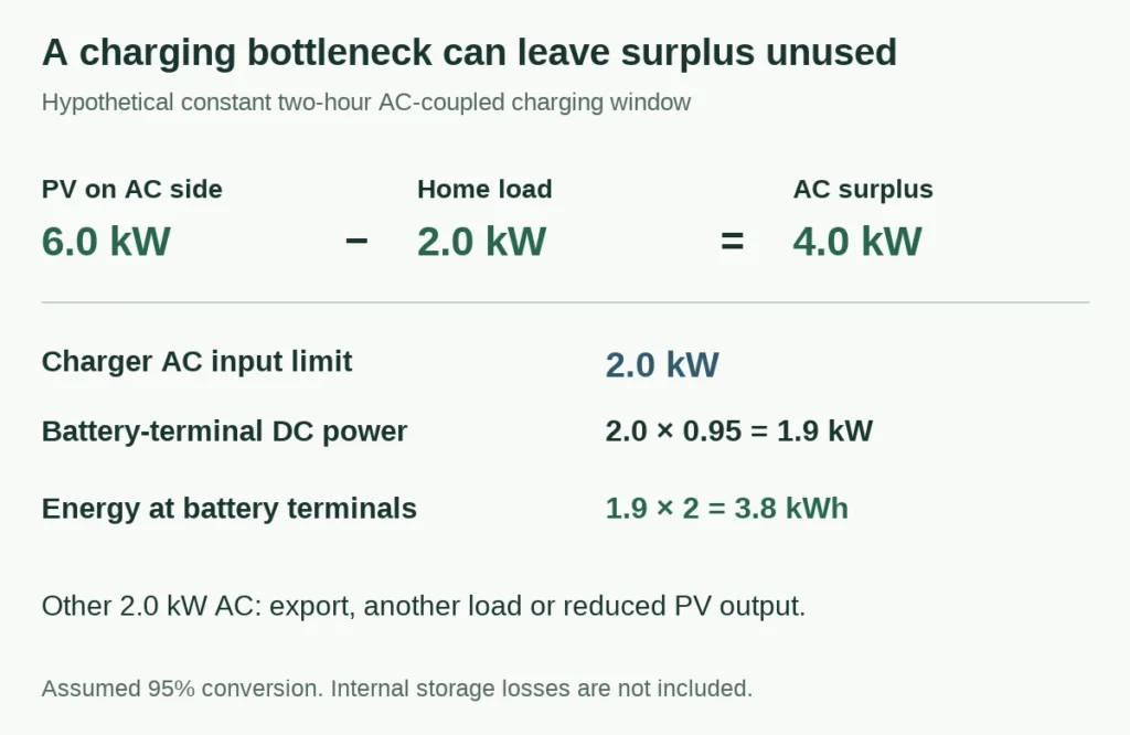
Figure 4. All inputs are assumptions. The 2kW limit is at the charger’s AC input; the 3.8kWh result is at the battery terminals, not later AC output.
For a DC-coupled proposal, identify its corresponding solar charging, converter and battery limits. A DC route can sometimes capture energy that would otherwise be clipped by the PV inverter, but only if the topology, controls and available battery headroom support that path. It cannot recover sunlight that the proposed route never makes available. The SAM DC-connected description treats clipped-energy charging as a specific enabled operating condition, not an unconditional result of the label.
Use interval generation and load records to find which limit matters at the site. A high annual solar total does not reveal whether surplus occurs while the battery can accept it. Once the route is established, the separate home battery sizing guide can help relate available energy to the intended loads and hours.
Define backup independently of normal grid operation
A system can reduce daytime export and supply evening loads while the grid is present, yet have a different or unsupported role when it fails. Backup requires an appropriate separation arrangement, equipment capable of supplying the local electrical reference where needed, and an approved set of loads. Continuing solar generation introduces another control requirement.
The Australian Government’s battery guidance distinguishes battery backup from an islandable arrangement that also uses solar during an outage. The U.S. Department of Energy’s solar resilience explanation likewise describes the need for suitable inverter and storage configuration. Their market examples do not establish a ZJBESS approval or a universal wiring method.

Figure 5. A battery adds an energy source. The complete design determines where that energy can be used and whether solar can contribute during an outage.
Write the outage promise in observable terms. Which circuits and phases receive power? What simultaneous and starting loads are covered? Is PV charging available during the outage? What happens after a low-energy shutdown? Transfer time and restart behaviour belong to the system specification, not to the battery’s kWh label.
A useful hypothetical distinction is a home whose battery supports selected lighting and refrigeration, while its original PV inverter shuts down during a grid failure. That may satisfy a limited battery-only backup brief, but it does not satisfy a promise of solar-supported operation throughout a long outage. Another properly designed arrangement may support both tasks. Neither conclusion follows from AC coupling alone.
Victron’s ESS design manual distinguishes PV connection positions and their requirements within its own system. This is a concrete reason to request the actual arrangement and applicable manuals. Do not copy its equipment ratios, settings or approvals to a different combination. Where uninterrupted or off-grid operation is central, use the off-grid and weak-grid project route to frame the requirements for technical review.
Account for an outage when the battery cannot absorb more
The difficult operating point is not always an empty battery. A full battery, a low household load and strong solar can leave generation with nowhere to go when export is unavailable.
For a power-balance illustration, assume all three values are expressed at the same local AC reference: PV could provide 4.0kW, loads use 1.0kW, and the permitted charging path can absorb 0.5kW. With no export or other sink, PV must be reduced by 2.5kW to balance this simplified system. The 0.5kW is an assumed AC-equivalent acceptance value, not a battery DC rating.

Figure 6. An invented instantaneous power balance, not a control setting or a frequency-shifting instruction. Actual controls and transient behaviour require approved design.
This explains why a backup proposal needs more than an energy-capacity calculation. The system must have a supported way to keep generation, loads and accepted charging in balance as they change. A battery can reduce its permitted charging because of state of charge, temperature or protection conditions; storage headroom and available charging power are different quantities.
Ask the technical designer how the proposed PV equipment is controlled in islanded operation, what happens when the battery limits charging, and how shutdown and restart are handled. A successful charging observation with the grid present cannot answer those questions. The required evidence should refer to the proposed mode and equipment versions. It should not rely on a general statement that two brands are compatible.
These are questions for the documented design and commissioning process. They are not instructions to disconnect the grid, remove communication cables or provoke a protective trip. The result needed for the purchasing decision is an agreed scope with traceable evidence, including any operating mode that remains unverified.
Keep coupling, battery voltage and communication separate
“AC-coupled” does not mean “high-voltage battery”, and “DC-coupled” does not mean “48V battery”. The first label describes the solar/storage relationship. The battery voltage class describes a different interface. Communication and operating-mode approval are further questions.
For example, ZJBESS publishes the LS15KW as 51.2V, 300Ah and 15.36kWh nominal. Those approved nominal values identify a battery product. They do not show that an existing PV inverter can charge it, that a named inverter’s battery input accepts it, or that a complete arrangement supports the promised backup mode. The LS15KW product page is a route to model information, rather than a substitute for the integration record.

Figure 7. Resolve each question at its own boundary. A match at one layer does not automatically resolve the others.
ZJBESS has confirmed that factory compatibility testing and customer-side validation exist. The applicable result still needs to be matched to the exact equipment and intended configuration; it is not a public approval of every model from a named inverter brand. An existing CAN or RS485 socket alone does not close that gap.
The home battery voltage explanation develops the current and conductor-loss consequences separately. Keep those calculations in the electrical-interface review rather than using the coupling label to select a voltage or promise a load capability.
Make the retrofit proposal answer the actual application
The comparison is ready for a decision when both proposals describe the same required outcome. A retention proposal should identify what stays and its supported role. A replacement proposal should show why the changed equipment solves a relevant constraint. A backup proposal needs a separate description of the loads and solar operation it supports.
| Item to align | What the two proposals should state |
| Starting installation | Existing PV and inverter models, supply phases and relevant equipment condition |
| Intended operation | Self-consumption, battery-only backup, solar-supported backup or a defined combination |
| Energy and power boundaries | Where energy is measured, charging/discharging limits and which losses are included |
| Equipment retained or added | Battery, conversion equipment, controls, metering, switching and included accessories |
| Responsibility and evidence | Who designs, approves and commissions the arrangement; applicable records and unresolved modes |
A cheaper quote can have a narrower task: perhaps it covers evening self-consumption while the other includes selected-circuit backup and its switching equipment. Resolve that scope difference before calling one architecture better value. Likewise, an efficiency advantage calculated from assumed factors cannot justify replacing sound equipment without comparing the complete project consequences.
For a battery enquiry, send ZJBESS the destination, existing PV/inverter model, intended operating modes, essential loads, available installation space and expected quantity. Include firmware information and a layout if available; ask the responsible technical parties to resolve the remaining integration details. The residential storage page provides the application route, and ZJBESS distributor support is the commercial route for a repeatable product range or multi-site order.
Keep the battery supply, complete system equipment and site work explicit in the quotation. This article explains the architecture choices; it does not authorize a configuration, define a wiring method or promise that every existing solar installation can be retrofitted in the same way.
Discuss Your ProjectBack to Blog

