
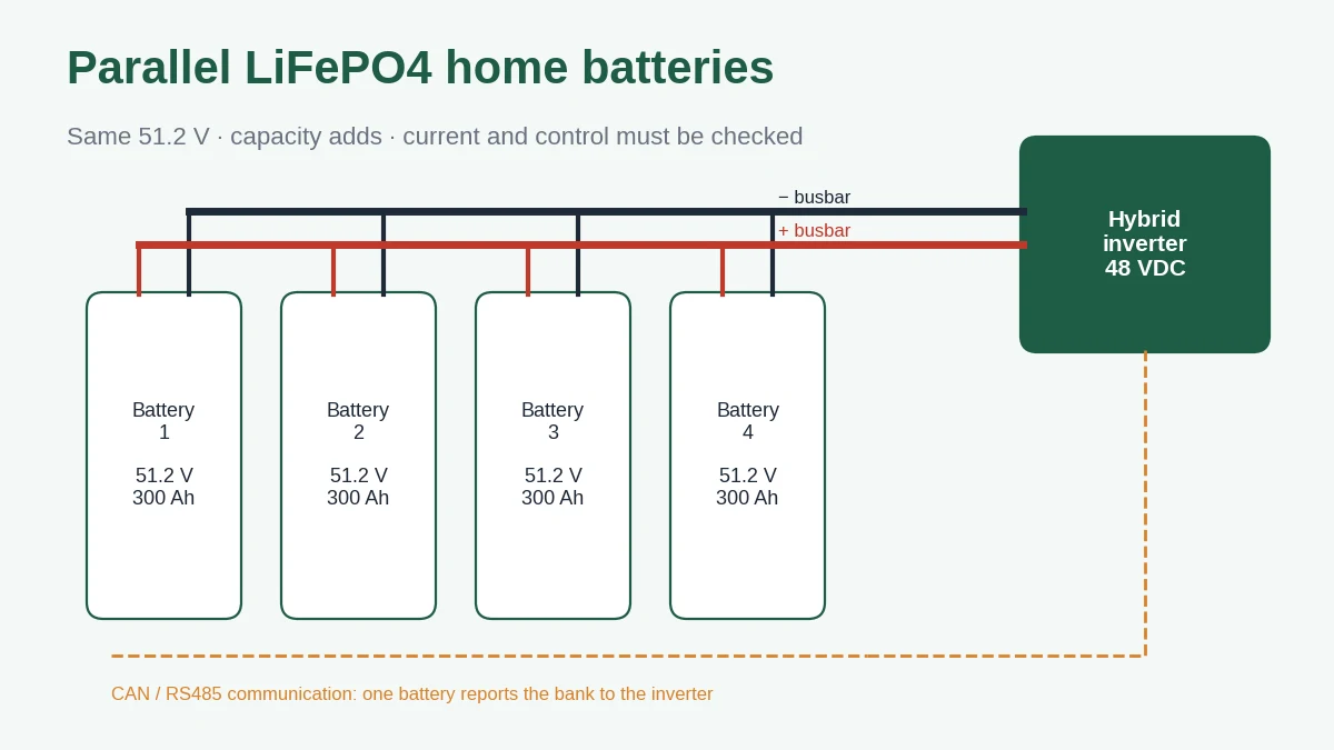
Connecting 51.2V LiFePO4 home batteries in parallel keeps the system at 51.2V and adds their amp-hours, so two 300Ah units give 600Ah and 30.72kWh nominal. The energy calculation is the easy part. A parallel bank also has to be checked for the current each unit carries, what happens when one unit drops offline, how evenly the cables share current, and whether the batteries and inverter agree on one set of limits. This guide works through each of those checks with numbers you can repeat for your own project.
The examples use the published values of the ZJBESS LS15KW 15.36kWh floor-standing battery (51.2V, 300Ah, ≤100A recommended charge current, ≤200A maximum continuous discharge current) and the MAX-II-13.2KW hybrid inverter (48VDC battery system, 160A maximum charging current). Any value marked “assumed” is an illustration, not a product setting.
What a parallel connection changes, and what it does not
In parallel, every battery’s positive terminal joins one positive bus and every negative terminal joins one negative bus. All units then sit at the same terminal voltage, and their capacity adds. In series, voltage adds and amp-hours stay the same. The two are not interchangeable: a 51.2V home battery is designed for a 48V inverter, and connecting such units in series to reach a higher voltage is outside that design unless the manufacturer documents it for the specific model.
| Configuration (LS15KW, nominal) | Voltage | Capacity | Energy |
|---|---|---|---|
| 1 unit | 51.2 V | 300 Ah | 15.36 kWh |
| 2 units in parallel | 51.2 V | 600 Ah | 30.72 kWh |
| 4 units in parallel | 51.2 V | 1,200 Ah | 61.44 kWh |
| 15 units in parallel (datasheet maximum) | 51.2 V | 4,500 Ah | 230.4 kWh |
These are nominal products of voltage and capacity. Usable energy at the AC outlet is lower once the SOC window, conversion losses and standby consumption are counted, as covered in the home battery sizing guide.
A parallel bank also does not raise AC output. Adding a third battery to a 13.2kW inverter gives more hours at 13.2kW, not more than 13.2kW. Output power is set by the inverter; the batteries only need to be able to supply the DC current it draws.
“Up to 15 units” is a battery-side ceiling, not a system rating
ZJBESS datasheets for its 51.2V home batteries state parallel connection of up to 15 units. That figure describes how many units the battery communication and BMS design can group. Whether a particular installation can run 15 units also depends on:
- the inverter’s own limit on how many battery units or how much capacity it will read over CAN or RS485, which varies by inverter brand and firmware;
- the busbar, cable and DC protection rating, which must carry the full bank current, including fault current;
- the BMS firmware version on every unit, since units must use the same protocol and addressing scheme;
- floor space, weight and service access for every cabinet.
Treat the 15-unit figure as the upper bound to plan within. The workable number for a given project is the lowest limit across the battery, the inverter and the DC installation.
Size the bank for current as well as kilowatt-hours
The battery must supply the inverter’s DC input current at its highest load and lowest battery voltage. A quick estimate divides AC power by battery voltage and conversion efficiency.
Worked example (assumptions stated): MAX-II-13.2KW at full 13,200W output; battery voltage assumed at 48V near the low end of discharge; conversion efficiency assumed at 0.93.
DC current ≈ 13,200 ÷ (48 × 0.93) ≈ 296 A.
One LS15KW: 296A against a ≤200A published maximum continuous discharge current. Not enough.
Two LS15KW, even sharing: about 148A each. Within the published value.

Charging works the same way. The MAX-II-13.2KW can deliver up to 160A of charging current, while the LS15KW recommended charge current is ≤100A per unit. With two units sharing evenly, each sees about 80A. With one unit, the inverter’s charge current limit has to be set at or below the battery’s recommendation, or controlled by the BMS over closed-loop communication. The inverter compatibility guide explains how closed-loop and open-loop control handle that limit.
This is why a customer who only needs 15kWh of energy may still need two batteries: the energy target is met by one unit, but the inverter’s peak current is not.
The same estimate across common single-phase inverter sizes gives a quick first screen. Run the energy calculation separately and take whichever count is higher.
| Inverter rated output | Estimated DC current at full output* | Minimum LS15KW units by current (≤200A each) | Units to stay within 200A with one offline |
|---|---|---|---|
| 5 kW | ≈112 A | 1 | 2 |
| 8 kW | ≈179 A | 1 (about 90% of the rating, little margin) | 2 |
| 10 kW | ≈224 A | 2 | 3 |
| 13.2 kW (MAX-II-13.2KW) | ≈296 A | 2 | 3 |
*Rated output ÷ (48V × 0.93), even current sharing. A screening estimate, not a configuration approval; surge loads, the inverter’s own battery current limit and the installed cabling can change the answer.
Check what the remaining units carry if one trips
A battery in a parallel bank can go offline for several reasons: its BMS opens on a temperature or cell-voltage protection, its breaker trips, or it is isolated for service. If the load stays the same, the remaining units share the same total current.
With n units sharing evenly, each carries roughly I ÷ n. After one drops out, each carries I ÷ (n − 1).
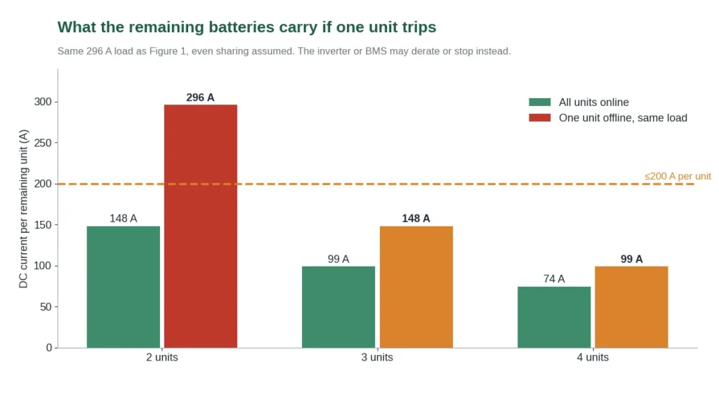
For the 296A example, a two-unit bank pushes the remaining battery to about 296A, well above its 200A rating. In that case the inverter or the remaining BMS will normally limit current or shut down, which means a backup outage at full load. A three-unit bank keeps the remaining two at about 148A each.
Whether this matters depends on the project. For a home that can tolerate a load shed when one unit faults, two units may be fine. For a clinic, a shop with refrigeration or a site with no grid, the n−1 case is worth sizing for. Either way, this is an engineering estimate under even sharing, not a redundancy guarantee; actual behaviour depends on the inverter and BMS response.
Why parallel batteries rarely share current evenly
Each battery and its cable form a separate path to the inverter. Current divides in inverse proportion to the resistance of each path, so the lower-resistance path carries more. Cable length, lug crimping, busbar take-off position, temperature and the battery’s own internal resistance all contribute.
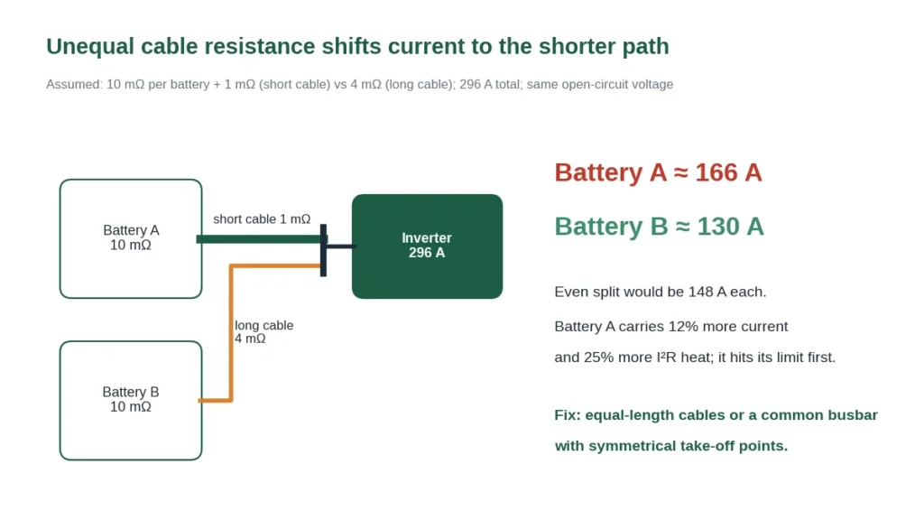
Worked example (assumed resistances): each battery 10mΩ; battery A cable 1mΩ, battery B cable 4mΩ; 296A total.
Battery A ≈ 296 × 14 ÷ (11 + 14) ≈ 166 A; battery B ≈ 130 A.
Battery A carries about 12% more current than an even split and about 25% more resistive heat (heat scales with current squared).
The 10mΩ figure is an assumption for illustration; the LS15KW datasheet lists internal resistance as ≤50mΩ at 50% SOC, which is a ceiling rather than a typical value. The point holds for any values: a few milliohms of difference in cabling matters because the battery resistance itself is small.
Practical layout follows from this. Use cables of equal length and cross-section from every battery to a common busbar, take the inverter feed from the busbar rather than from one battery’s terminals, and torque every connection to the value in the installation manual. Daisy-chaining batteries terminal-to-terminal and feeding the inverter from the first unit is the arrangement most likely to overload that unit, because every jumper adds resistance to the paths of the units further down the chain.
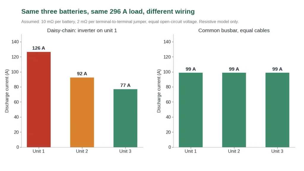
In this three-unit example, the first unit in a daisy chain carries about 126A while the last carries 77A. The bank looks lightly loaded on average, yet unit 1 reaches its limit, warms faster and ages faster than the others. With a common busbar and equal cables, each carries about 99A. The article on battery voltage, current and cable loss explains the I²R relationship in more detail.
Protect each battery branch, not only the bank
A breaker between the busbar and the inverter protects the inverter cable. It does not protect an individual battery cable. If one battery cable or terminal faults, every other battery in the bank can feed current into that fault through the busbar, and the main breaker may not see it at all because the fault current never passes through it.
For that reason, each battery branch normally has its own overcurrent protection and a way to isolate it, sized for that branch’s cable. Some battery models include a DC breaker on the front panel; whether that breaker is rated to serve as branch protection in a multi-unit bank, and what main protection the bank needs, should be taken from the installation manual and the local electrical code. This article does not specify cable sizes or breaker ratings, because they depend on the cable run, installation method and local rules.
Branch isolation also makes service practical: one unit can be taken out for inspection while the rest stay connected, which is where the one-unit-offline check above becomes relevant.
Bring every unit to the same state before connecting
At the moment two batteries are joined, a voltage difference between them drives current from the higher unit to the lower one. Only the loop resistance limits that current, so a small voltage gap can produce a large current.
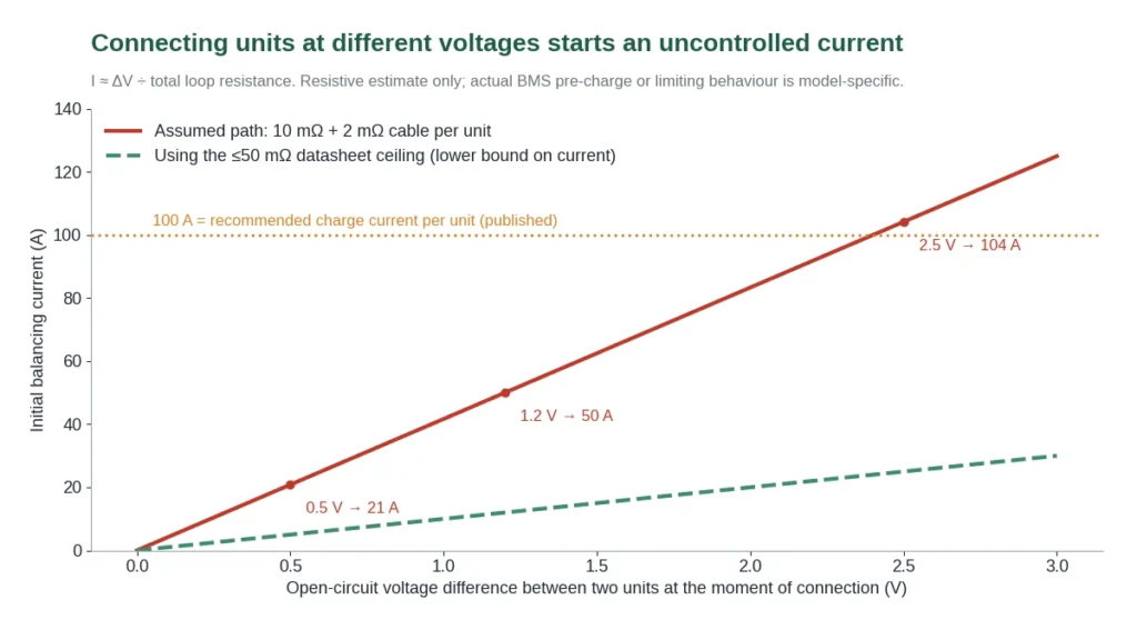
Estimate: I ≈ ΔV ÷ (Rbattery 1 + Rbattery 2 + Rcables).
With an assumed 24mΩ loop, a 1.2V difference gives about 50A and a 2.5V difference about 104A, above the 100A recommended charge current of the receiving unit.
LiFePO4 makes this harder to judge because its voltage curve is flat through the middle of its range. Two units can read within a few tenths of a volt and still be tens of percent apart in SOC; near full or empty, the same SOC gap shows up as a much larger voltage gap. The LiFePO4 state of charge guide explains why voltage is a weak SOC indicator.
The reliable approach is to bring every unit to the same defined state before closing the parallel connection, usually fully charged individually, and then connect with the inverter off and breakers open. Follow the voltage-matching procedure and tolerance in the ZJBESS installation manual for the specific model; this article does not set a threshold. Some BMS designs include pre-charge or current limiting at connection, but that behaviour is model-specific and should be confirmed rather than assumed.
Adding a new battery to an older bank
The most common expansion question is whether a battery bought today can be added to one installed two or three years ago. It often can, but the result is not the same as two new batteries.

Illustration (assumed ageing): aged unit at 85% of 300Ah = 255Ah with 13mΩ internal resistance; new unit 300Ah at 10mΩ.
Nominal sum: 555Ah × 51.2V ≈ 28.4 kWh, compared with 30.72kWh for two new units.
At 296A total, resistance split: new ≈ 167A, aged ≈ 129A.
Three effects follow. Capacity roughly adds, but the bank’s usable window is set by whichever unit reaches its cut-off first. The newer, lower-resistance unit carries more current, so the bank’s current limit is reached earlier than the nominal rating suggests. And because the two units age differently, their individual SOC readings can drift apart, which shows up as inconsistent SOC on the inverter or app.
Before quoting an expansion, collect from the existing installation: model and serial number of every unit, installation date, BMS firmware version, cycle count and capacity data from the app or screen if available, and the inverter model and firmware. Send these with the expansion request so ZJBESS can confirm whether the pairing and firmware are compatible. Same voltage is not enough: the LS15KW (300Ah) and LS16KW (314Ah) are both 51.2V floor-standing units, but mixing them should still be confirmed for the specific firmware rather than assumed.
Mixing units also interacts with warranty records. Keep the serial numbers and installation dates of each unit separate, so a later claim can be traced to the right battery. The warranty claims guide lists what a claim record needs.
Set up communication so the inverter sees one bank
In a closed-loop system, the inverter does not talk to every battery. One battery acts as the master: it collects data from the other units and reports the bank’s SOC, charge voltage request, charge and discharge current limits and alarms to the inverter over CAN or RS485. The LS15KW provides CAN, RS485 and RS232 ports, and its datasheet describes selecting the inverter protocol from the battery’s screen.
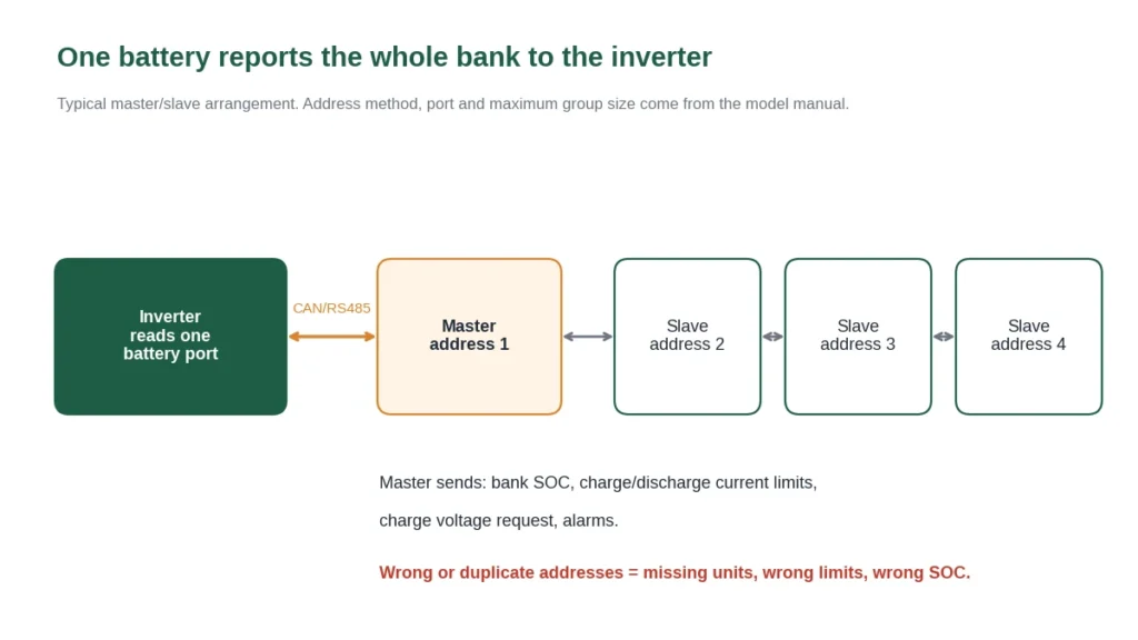
Three settings decide whether this works. Every unit needs a unique address, set by DIP switch, screen menu or automatic assignment depending on the model. The inverter cable must go to the designated master port with the correct pinout. And every unit should run compatible BMS firmware. Typical symptoms of a wrong setup are the inverter showing fewer batteries than installed, a current limit that matches one unit instead of the bank, or an SOC that jumps when a unit is added. Confirm the addressing method and maximum group size in the manual for the model you are installing.
One large battery or several smaller ones?
The same energy can often be built either way, and the choice is mostly about current. The published per-unit current ratings of the models below are the same, so splitting the energy across more units raises the bank’s total current capability.
| Published values | 1 × LS20KW floor-standing | 2 × BG10KW wall-mounted |
|---|---|---|
| Nominal energy | 20.48 kWh (51.2V, 400Ah) | 2 × 10.24 = 20.48 kWh (51.2V, 2 × 200Ah) |
| Maximum continuous discharge current | ≤200 A | ≤200 A per unit, about 400 A combined with even sharing |
| Recommended charge current | ≤100 A | ≤100 A per unit, about 200 A combined |
| Gross weight | 160 kg, one unit | 86 kg per unit |
| Against the 13.2kW example (≈296 A, 160 A charge) | Discharge current above the published rating; charge must be limited to 100 A | About 148 A discharge and 80 A charge per unit |
For the 13.2kW inverter, two smaller units meet the current requirement where one large unit of the same energy does not. The trade-off is more installation work: two sets of cables, two branch protections, communication addressing and a wall that can carry each unit, which the wall-mounted installation checklist covers. One large unit is simpler where the inverter is smaller, for example 5kW, where a single unit’s current rating already has margin. Gross weight is shipping weight; use the installation documents for mounting loads.
Product pages for comparison: LS20KW 20kWh floor-standing battery and BG10KW 10kWh wall-mounted battery.
Decide the final bank size at the first installation
Some parts of a parallel system are fixed on day one and are expensive to change later. If the customer expects to expand, plan these for the final size rather than the initial one:
| Decide now | Why it is hard to change later |
|---|---|
| Busbar and main DC cable rating | Must carry the full bank current; replacing it means shutting down and re-terminating every unit. |
| DC breaker or fuse between bank and inverter | Rating and interrupting capacity depend on the final number of units. |
| Floor space and access | An LS15KW measures 1000 × 500 × 300 mm with a 121 kg gross weight; each added unit needs its own footprint and service clearance. |
| Model and firmware family | Buying the expansion units within the same model and firmware generation avoids most mixing questions. |
| Inverter battery limit | Check the inverter’s maximum supported battery count or capacity before promising the customer a future size. |
If the expansion is likely within a year, it is often cheaper to install the full bank at once, both for current-sharing reasons and to avoid mixing units of different ages. The rack, wall and floor-standing comparison covers how each format scales.
Worked example: sizing a bank from start to finish
Putting the checks together for one hypothetical project shows how each step can change the answer. All inputs are assumptions for illustration.
Project: MAX-II-13.2KW inverter; overnight backup of 2.5kW average load for 10 hours = 25kWh AC; the owner wants the system to keep running if one battery trips.
1. Energy. Assume a 90% usable SOC window and 0.93 discharge efficiency: 25 ÷ (0.90 × 0.93) ≈ 29.9kWh nominal. Two LS15KW (30.72kWh) just cover it.
2. Current. At full 13.2kW output ≈296A. Two units ≈148A each, within the 200A published rating.
3. One unit offline. With two units, the remaining one would see ≈296A, so the bank would derate or stop. Three units keep the remaining two at ≈148A each.
4. Charging. 160A maximum charging current across three units ≈53A each, within the 100A recommendation.
Result: three LS15KW, 46.08kWh nominal. Energy alone suggested two; the one-unit-offline requirement set the final number.
If the owner accepts a load shed when one battery trips, two units are the lower-cost answer, and a third can be added later only if the busbar, protection and space were planned for it from the start. Writing both options into the quotation, with the reason for each, makes the difference clear to the customer.
Commissioning checks before handing over
- All units are the same model and firmware, or the mixed configuration has been confirmed in writing.
- Each unit was brought to the same state individually before the parallel connection was closed.
- Cables from each unit to the busbar are equal in length and size, and every terminal is torqued to the manual value.
- Each battery branch has its own protection and isolation as specified in the manual, and the main DC protection is rated for the final bank size.
- Addresses are unique, the master is connected to the inverter, and the inverter shows the correct number of units and total capacity.
- The charge and discharge current limits shown on the inverter match the bank, not a single unit.
- Under a real load, current per unit (from the app, screen or a DC clamp meter) is reasonably close across units. Record these values with the serial numbers for the handover file.
Reading common parallel-bank symptoms
Most problems in a parallel bank show up as a mismatch between units. The table pairs each symptom with the check that separates likely causes. It is a starting point for diagnosis, not a repair procedure; anything involving opening a battery or changing BMS settings goes through ZJBESS support.
| Symptom | Common causes | First check |
|---|---|---|
| Inverter shows fewer units or less capacity than installed | Duplicate or missing address; inverter cable on a slave port; firmware mismatch | Address of every unit, port used by the inverter cable, firmware version on each screen |
| Units show different SOC after a few days | Unequal cable resistance; different ages or capacities; SOC estimate drift | Current per unit under the same load; cable lengths; whether the gap closes after a full charge |
| One unit is noticeably warmer | It carries more current (shorter cable, daisy-chain position, lower resistance); a loose terminal | Current per unit; terminal temperature and torque with the system isolated |
| Bank shuts down at high load while SOC is still high | One unit reaches its current limit first and the BMS opens; the others then exceed theirs | Which unit alarmed first in the log; per-unit current at that load |
| Charge current is lower than the inverter setting | The master BMS is requesting a lower limit, for example due to temperature or a unit near full | Charge current limit shown on the inverter’s BMS page; cell temperatures |
| Large current flow when a unit is reconnected | The unit was at a different voltage from the bank | Bring it to the same state before reconnecting, as described above |
For SOC gaps specifically, the SOC guide explains how to collect a time-aligned record before changing any settings.
Frequently asked questions
How many ZJBESS 51.2V batteries can be connected in parallel?
The datasheets state up to 15 units. The usable number for a project is also limited by the inverter’s supported battery count, the DC busbar and protection rating, and the BMS firmware, so confirm the configuration for your inverter before quoting.
Does connecting batteries in parallel increase inverter output?
No. Parallel batteries add energy (more hours of runtime) and share the DC current. AC output power is set by the inverter’s rating.
Can I connect 51.2V home batteries in series for a high-voltage inverter?
Not unless the manufacturer documents series operation for that model. 51.2V home batteries are designed for 48V inverters; series connection changes insulation, BMS and protection requirements.
Can I add a new battery to one that is several years old?
Often yes, but capacity and current sharing will be uneven. Send the model, serial number, installation date, firmware and cycle data of the existing units so compatibility can be confirmed first.
Do batteries in parallel need to be the same capacity?
Same model and firmware is the safest arrangement. Units of different capacity can share a bus electrically, but they reach full and empty at different times and share current unevenly, so mixed capacities should only be used where the manufacturer has confirmed the combination.
Does each battery in a parallel bank need its own breaker or fuse?
Normally yes. A main breaker protects the inverter cable, but a fault on one battery cable can be fed by all the other batteries without passing through it. Size branch protection from the installation manual and local electrical code.
Is one large battery better than two smaller ones of the same kWh?
Not automatically. When the per-unit current rating is the same, two smaller units give roughly twice the combined charge and discharge current, which suits larger inverters. One large unit means less wiring and fewer connections, which suits smaller inverters with current margin.
Why does my inverter show only one battery after installing three?
Usually a communication setup issue: duplicate or missing addresses, the inverter cable on the wrong port, or mismatched firmware. Check the addressing method in the model manual.
Request a parallel configuration from ZJBESS
For a parallel or expansion quotation, send the inverter brand, model and firmware; the peak and continuous load; the target backup time; the number of units now and at final size; and, for expansions, the serial numbers and firmware of the existing batteries. ZJBESS will reply with the model combination, communication settings and documents for that configuration. Distributors can also review the distributor support terms or contact the sales team directly.
Discuss Your ProjectBack to BlogSources: ZJBESS LS15KW 15.36kWh datasheet (nominal voltage, capacity, charge and discharge current, internal resistance, communication, dimensions, gross weight, parallel count); ZJBESS LS20KW and BG10KW datasheets (nominal capacity, current ratings, gross weight); ZJBESS MAX-II-13.2KW product page (48VDC battery system, 160A maximum charging current). All currents in worked examples are estimates from stated assumptions, not measured values or settings.


