

Two home batteries can store the same nominal energy yet place very different demands on an inverter. A higher battery voltage reduces the DC current needed at the same power. That changes conductor losses and the operating conditions of power electronics, but it does not, by itself, prove longer backup time, better whole-system efficiency or compatibility.
To understand low-voltage and high-voltage home batteries, follow three separate quantities: energy in kWh, power in kW and the voltage at which that power flows. The relationships below explain why a 51.2V cabinet and a several-hundred-volt battery system are different electrical architectures, even when their energy labels look similar.

Voltage, amp-hours and energy describe different things
Voltage describes the electrical potential difference across the battery terminals. Amp-hours describe charge capacity on a specified rating basis. Energy describes the quantity stored or transferred. For a nominal-energy comparison, multiply nominal voltage by rated amp-hours and divide by 1,000. Comparing Ah alone across different voltages can make a lower-voltage battery appear much larger even when the nominal energy is the same.
Consider two invented battery configurations:
| Quantity | Configuration A | Configuration B |
| Nominal voltage | 51.2V | 409.6V |
| Rated capacity | 200Ah | 25Ah |
| Calculated nominal energy | 10.24kWh | 10.24kWh |
The arithmetic is 51.2 × 200 ÷ 1,000 = 10.24kWh and 409.6 × 25 ÷ 1,000 = 10.24kWh. The eightfold difference in voltage offsets the eightfold difference in Ah. Neither calculation establishes usable energy, output power or compatibility.

Figure 1. Equal calculated nominal energy does not make two DC interfaces interchangeable. The configurations are hypothetical.
Keep the energy boundary consistent when reading real offers. One supplier may state nominal battery energy; another may publish DC usable energy under specified test conditions. An AC-delivered value includes a different system boundary again. Do not rank those values as though all represented the same service to the customer. The home battery sizing guide deals with the load and discharge-window calculation after that boundary is defined.
Battery voltage also changes during operation. A nominal figure is useful for the arithmetic above, while an actual input-range check needs the permitted operating range and applicable conditions. Matching one nominal point does not show that the pairing remains supported over the intended charge and discharge cycle.
In home-storage catalogues, low-voltage often describes a 48V-class battery interface, while high-voltage describes substantially higher battery voltages. These labels are not a universal legal safety classification. A PV input, MPPT voltage range or 230V AC output is a different interface; none identifies the required battery voltage.
At the same DC power, higher voltage means lower current
For a steady DC operating point, power equals voltage multiplied by current. Dividing power by voltage gives the current at that point. The voltage must be the operating value, rather than a nominal label silently treated as constant throughout discharge.
To isolate the relationship, assume a steady 5.12kW measured at each battery’s terminals. Hold the working voltages at 51.2V and 409.6V for this calculation only:
- At 51.2V: 5,120W ÷ 51.2V = 100A.
- At 409.6V: 5,120W ÷ 409.6V = 12.5A.
The eightfold voltage increase reduces current to one eighth. It does not establish that either invented configuration can supply 5.12kW. A real operating point remains subject to the battery’s current limits, BMS permissions, temperature, state of charge and inverter limits. The calculation is on the DC side and does not establish an AC output rating.
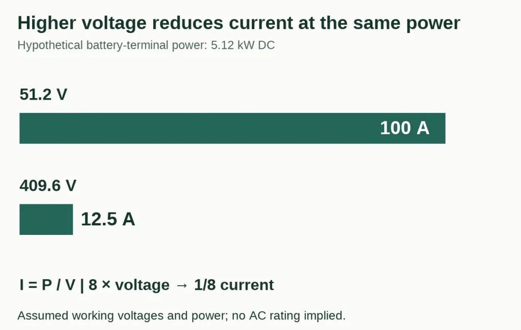
Figure 2. The power and working voltages are assumptions. Actual equipment ratings still govern.
The same relationship explains why current headroom can shrink as battery voltage falls. If an inverter maintains a defined power while its DC input voltage decreases, it needs more current. A current or voltage limit can restrict output before the energy store is empty. A kWh label therefore cannot answer a simultaneous-load question.
Do not transfer the numerical current advantage into a cable size. Required conductor area, protection and installation methods depend on the approved equipment, route, temperature, fault conditions and applicable rules. Lower calculated current is an engineering input, not a completed installation design.
Resistive loss changes with the square of current
A resistive path dissipates power as heat according to I²R. The path includes more than a length of cable: connections and other components contribute resistance. Victron’s Wiring Unlimited explains these contributions and their effect on voltage drop. Its equipment guidance does not replace another manufacturer’s instructions.
Continue the hypothetical operating points above and assign both complete conductor paths the same invented resistance of 0.010 ohm. This deliberately holds resistance constant so that only the current effect changes.
| Calculated quantity | 51.2V case | 409.6V case |
| Current at battery terminals | 100A | 12.5A |
| Assumed total conductor-path resistance | 0.010 ohm | 0.010 ohm |
| Resistive loss, I²R | 100W | 1.5625W |
| Voltage drop, IR | 1.000V | 0.125V |
The loss ratio is 100 ÷ 1.5625 = 64. The current ratio was eight; squaring it gives 64. This ratio applies to the one modelled loss term. It is not a 64-fold improvement in inverter efficiency or a prediction of annual savings.

Figure 3. Holding resistance equal isolates the current effect. Real systems can use different conductors, connections and conversion stages.
Because 5.12kW was defined at the battery terminals, the receiving end gets 5,020W in the 51.2V case and approximately 5,118.44W in the 409.6V case, before inverter losses. If the task were instead to deliver exactly 5.12kW at the inverter input, these currents would need recalculating. Changing the measurement boundary changes the problem.
Real designs do not necessarily hold resistance equal. A lower-voltage design can use a shorter path or a larger conductor area. A higher-voltage design has its own connection, insulation and protection requirements. High current makes path resistance more consequential; it does not establish that every higher-voltage product outperforms every lower-voltage product.
Voltage drop and battery voltage decline are different effects
Cable-path drop is the difference between two points under current. Battery terminal voltage also changes with operating conditions. Combining the two into a vague description of a weak battery can lead to the wrong diagnosis.
In the 51.2V example, 100A through 0.010 ohm creates a 1.0V drop. An idealized battery-terminal reading of 51.2V therefore corresponds to 50.2V at the receiving end. At the assumed higher-voltage point, the drop is 0.125V and the receiving voltage is 409.475V. Neither value predicts an actual device’s alarm threshold.
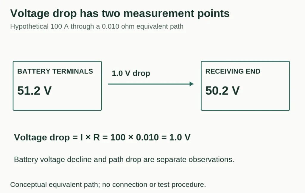
Figure 4. Compare defined measurement points at the same operating condition. This equivalent-path explanation is not a wiring diagram.
For a defined, approximately constant inverter input power, falling input voltage calls for rising current. That current creates additional resistive drop and heating. Actual control behaviour and protection determine how far operation continues; this relationship alone does not prove instability or a faulty component.
Separate three observations. If battery-terminal voltage declines while the difference across the path stays small, the observation points somewhere different from a large difference between the battery terminals and inverter input. If a BMS current limit is reached, that is another distinct constraint. More than one can occur together. A single inverter display value cannot identify the cause by itself.
Measurements around live equipment belong to qualified personnel following the applicable procedure. A useful record identifies measurement points, load, time, state of charge, temperature and reported limits. It does not turn one voltage reading into a conclusion about an entire battery shipment.
Battery voltage is only one part of the inverter’s conversion path
A household battery supplies DC; household AC is produced by controlled power conversion. The battery port and the inverter’s internal DC link need not operate at the same voltage. Depending on the design, voltage conversion and isolation can take place in different stages.
Texas Instruments’ TIDA-010933 reference design illustrates an implementation using an isolated DC/DC topology and DC/AC conversion, with 48V battery-storage capability. It is an engineering reference, not evidence of the internal construction or approval of a ZJBESS inverter pairing.
Nor does a higher-voltage battery automatically remove DC/DC conversion. TI’s TIDA-010938 reference design includes a bidirectional DC/DC stage configurable for battery voltage ranges and a separate DC/AC stage. Its published power figures do not describe the equipment in a home battery quotation.
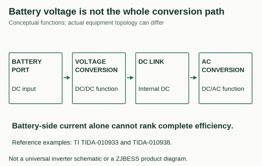
Figure 5. A conceptual conversion path. Actual equipment can combine or arrange functions differently; this is not a universal inverter schematic.
Each stage has operating limits and losses. Changing battery voltage can change current and conversion ratio at one stage, but complete performance also depends on topology, devices, controls and operating point. Counting stages, or comparing battery-side current alone, cannot determine the efficiency winner.
PV and battery ports also perform different jobs and can have different permitted ranges. GoodWe’s Battery Compatibility Overview, version 20260910-EN-V029.1, separates low-voltage and high-voltage system families. It does not demonstrate ZJBESS approval. The existing LiFePO4 inverter compatibility guide covers the specific pairing task.
A module voltage is not always the assembled system voltage
A module’s voltage does not necessarily describe the assembled battery’s external interface. A high-voltage product can contain modules whose individual nominal voltage resembles that of a low-voltage cabinet. Its approved assembly, controller and inverter connection define a different system.
BYD provides a concrete example in its Battery-Box Premium HVM datasheet for BCU2.0. The sheet identifies an HVM module at 51.2V nominal while listing the three-module HVM 8.3 system at 153.6V nominal, with an operating range of 120–177V. Those published figures describe that BYD product architecture. They do not authorize assembling unrelated 51.2V cabinets into a tower or connecting them to its inverter combinations.
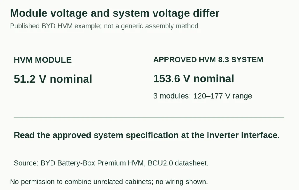
Figure 6. Identify the module and the approved assembled system separately. This conceptual diagram is not a wiring or assembly instruction.
The distinction matters when interpreting expansion. A module may be a component that requires a particular control unit and an approved minimum configuration. An additional module may change both energy and system voltage in one architecture, while a different architecture expands differently. A physical stack is not enough to identify the electrical arrangement.
The manufacturer’s configuration record must cover the actual quantity and control equipment. BYD’s HVS/HVM compatible inverter list V2.22, updated October 10, 2026, lists module quantities and minimum firmware by inverter. It demonstrates why the permitted assembly matters; its quantities and settings apply to the named combinations, not ZJBESS products.
Do not use the generic low-voltage label as permission for DIY changes. High current at lower voltage still creates serious fault and heating hazards. Higher-voltage systems add different insulation, isolation and service requirements. Follow the approved equipment design and applicable installation requirements rather than trying to convert one architecture into another with a cabinet count or cable change.
A smaller conductor loss is not better round-trip efficiency
Efficiency needs a defined input and output. An inverter’s conversion efficiency at one operating point, a battery’s DC energy efficiency and a complete system’s AC round-trip efficiency cover different processes. They should not share a comparison column without explaining those boundaries.
For example, assume a complete system takes 10.0kWh from its defined AC input during charging and later returns 8.8kWh to its defined AC output, with matched starting and ending battery state and no other energy flows. Its calculated AC round-trip efficiency is 8.8 ÷ 10.0 = 88%. These invented figures do not describe either voltage class or any named product.
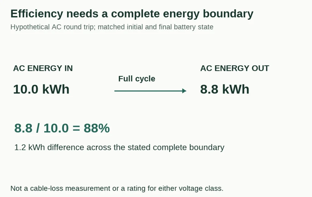
Figure 7. State the complete cycle and energy boundary. This example is unrelated to the earlier instantaneous conductor-loss calculation.
The 1.2kWh difference can include losses across charging, storage, discharging and auxiliaries within that boundary. It cannot be assigned entirely to the battery cables. A higher-voltage system could reduce one resistive contribution while another loss increases elsewhere; evidence covering the complete task is needed to establish the result.
Load level and time matter too. A constant auxiliary power draw uses energy over the whole observation period. A brief maximum-efficiency point cannot describe an overnight period with changing loads and standby time. Align the energy boundary, operating profile, initial and final state, and treatment of auxiliary consumption before comparing results.
Applying the physics to a 51.2V home battery
ZJBESS publishes 51.2V nominal for the BG10KW wall-mounted battery, LS15KW floor-standing battery and LS20KW floor-standing battery. Their respective nominal energy figures are 10.24, 15.36 and 20.48kWh. Within this group, the larger kWh figure does not mean a higher nominal voltage.
It also does not establish a proportional rise in permitted output power. Energy, the applicable current limits and inverter operation remain separate parts of the assessment. None of the hypothetical current, resistance or efficiency inputs in this article is a ZJBESS specification. These cabinets are not being offered as components for a high-voltage conversion.
For a technical enquiry, send the full inverter model, intended operating mode, selected loads and battery model through ZJBESS distributor support. Request the applicable configuration and evidence for its voltage range, current limits and pairing. If the task is estimating backup hours, use the sizing guide; if it is proving a specific pairing, use the compatibility guide. Those are the next calculations after the voltage architecture is understood.
Discuss Your ProjectBack to Blog

